EAGLE, short for the Easy Applicable Graphical Layout Editor, is powerful PCB design software tailored to meet the needs of professional engineers, makers and those at school.
The simplicity of the software provides a fast learning curve, even for those new to PCB design. The openness of EAGLE design resources, such as its extensive and fully-open component libraries, eases the design process for all.It has three modules: Schematic Editor, Layout Editor and Autorouter. Each of these modules features different roles in PCB design:
1) Layout Editor allows you to design PCBs comes with the Library Editor, the Computer Aided Manufacturing (CAM) Processor, and the Text Editor. With the Library Editor you can already design Packages (footprints), Symbols and Devices (for a schematic). The CAM Processor generates the output data for PCB production (e.g. Gerber or drill files). It is also possible to use User Language programs and Script files.
2) Schematic Editor is applicable for drawing electrical wiring diagrams. The Schematic Editor comes, as well as the Layout Editor, with the full Library Editor for designing Symbols for the Schematic and Packages for the Layout, with the CAM Processor, and the Text Editor. You can also use User Language programs and Script files.
3) With Autorouter module, you can have airwires routed automatically. Simply choose single nets, groups of nets or all nets for the automatic routing pass, the program will handle various network classes having different track widths and minimum clearances.
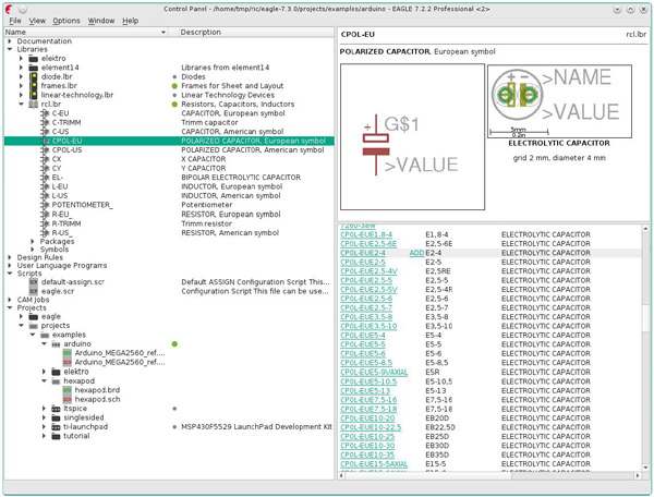
Control Panel
The Control Panel normally appears after starting EAGLE, and this is the program's control center. The entire files specific to EAGLE are managed here, and some basic settings can be made. It is similar to the familiar file managers used by a wide variety of applications and operating systems. Each EAGLE file is displayed in the tree view by means of a small symbol. The tree structure provides a quick overview of the libraries, Documentation, Design Rules, User Language programs, script files, CAM jobs and projects. A context menu is opened by clicking with the mouse on an entry in the tree view. This allows you, depending on the object, to carry out a variety of actions, like rename, copy, print, open, create new etc. Graphics or PDF files, for example, will be opened with the default application.
Schematic Editor
The Schematic Editor window opens when you load an existing schematic or create a new one. There are several ways of opening files in EAGLE. You can, for instance, load a schematic diagram by means of the File >> Open >> Schematic menu in the Control Panel. Alternatively double click onto a schematic diagram file in the tree view. If you want to create a new schematic, select the menu File >> New >> Schematic . This will open a schematic with the name untitled.sch in the current project directory.
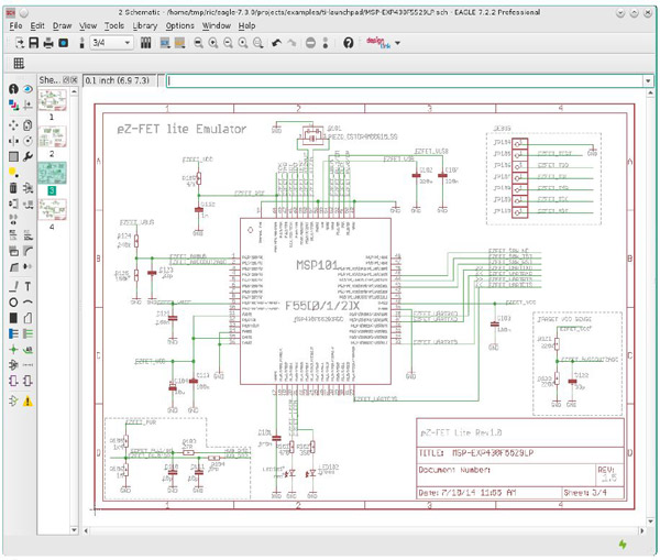
On top you can see the title bar, the menu bar, and the action toolbar. Below the action toolbar there is the parameter toolbar, which contains different icons, depending on the active command. Above the working area you will find the coordinate display on the left, with the command line, where commands can be entered in text format, to the right of it. On the left of the work space you find the command toolbar, which contains most of the Schematic Editor's commands. In the status line, at the bottom of the screen, instructions for the user appear, if a command is active.
EAGLE accepts commands in different but equivalent ways: as mouse clicks, text via keyboard, or from command (script) files.
Layout Editor
The Layout Editor window opens when you open an existing board file or create a new board. If you own the Schematic Editor you will normally draw a schematic first and then generate the circuit board file with the BOARD command, or by clicking the Board icon. This Layout Editor window appears very much like the Schematic Editor window and most of the information of Schematic Editor applies to the Layout Editor, too. Only some commands are different from those of the Schematic Editor.
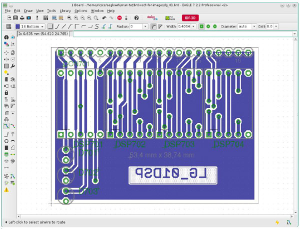
Some of the main commands on the Layout Command Toolbar are shown below:
1). 
It shows the properties of the selected object. Typing INFO IC1 in the command line results in the properties dialog of the object named IC1. Depending on the selected object some of the properties can be altered here.
2). 
It highlights the object to be selected with the mouse. It's also possible to enter the object's name (even several names at once) in the command line. * and ? are allowed to be used as wildcards, as well. Ctrl + SHOW toggles the show state of the selected object.
3). 
The following mouse click defines the new origin for the coordinate display. Relative coordinates (R x-value y-value) and polar values (P radius angle) are shown in addition to absolute coordinates in the coordinate display box. If you first click the MARK icon and then the traffic-light icon, only the absolute coordinate values will be displayed again.
4). 
Move any visible object. The right mouse button rotates the object.
5). 
It copies parts and other objects. When copying objects, a new name will be assigned, but the value will be retained. When copying a single wire, the copy will have the same name. Keep the Ctrl key pressed while clicking onto an object and the object will be grabbed at its origin. So it will be placed in the currently chosen grid. COPY can be used with groups. The group will be put into the clipboard of the operating system. It is possible to copy it into another EAGLE program, for example.
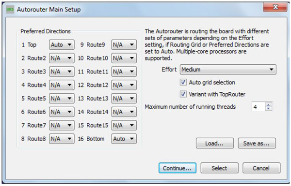
Autorouter
When running the Autorouter with the AUTO command, the setup menu appears first. All the necessary settings are made there.
This is where you specify the layers that may be used for routing and which preferred directions apply. Click in the appropriate combo box with the mouse, and select the desired value.
The main features of EAGLE Autorouter include:
• Any routing grid (min. 0.02 mm)
• Any placement grid
• Fully integrated into basic program
• TopRouter with gridless routing algorithm, which can be preceded by the Autorouter
• Optional automatic selection of routing grid and preferred directions in the signal layers
• Support for multi-core processors to process multiple routing jobs simultaneously
• SMDs are routed on both sides
• The whole drawing area can be the routing area (provided enough memory is available)
• The strategy is selected via control parameters
• Simultaneous routing of various signal classes with various track widths and minimum clearances
• Common data set (Design Rules) for the PCB Design Rule Check and the Autorouter
• Multilayer capability (up to 16 layers can be routed simultaneously, not only in pairs)
• Support of Blind and Buried vias
• The preferred track direction can be set independently for each layer: horizontal and vertical, true 45/135 degrees (important for inner layers!)
• Ripup and retry for 100% routing strategy
• Optimization passes to reduce vias and smooth track paths
• Prerouted tracks are not changed
• Serve a basis for the Followme router, a special operating mode of the ROUTE command that allows automatic routing of selected signals