With the escalation of complexity of PCB design, stable and reliable power supply has become a new trend of research on high-speed PCB design. Especially when the number of switching components keeps constantly improving and Vcore constantly decreasing, the fluctuation of power tends to bring deadly influence to system. Therefore, it has become a key point in high-speed PCB design to maintain the stability of power system.
However, as a result of the existence of power system impedance, relatively large voltage drop is generated by load transient current in power system impedance, which leads to instability of the system. In order to ensure that normal power is supplied to each component from the beginning to the end, the impedance in power system has to be controlled, which means that the impedance should be decreased as much as possible.
The application of decoupling capacitor is an effective way to prohibit the impedance in power system. This article analyzes the reasons for impedance prohibition in power system by decoupling capacitor and lists methods in terms of decoupling capacitor selection. Moreover, it mainly researches on how to determine the position of decoupling capacitor based on harmonic analysis to maximize the impedance prohibition in power system.
Impedance Analysis
Power and ground can be regarded as a large plate capacitor whose capacity is calculated based on formula C=kAr/d
In this formula, k is 0.2249 inch; A refers to the parallel area between two planes; r refers to the dielectric constant of medium and it's 4.5 for commonly-used FR4 board material; d refers to the distance between power and ground. A PCB with the size of 2x1inch is picked up as an example. The capacitance of capacitor formed by power and ground with a parallel area of 20Mils is approximately 0.2249x4.5x2x1/0.02=101.2pF. Based on this formula, it can be indicated that the decoupling capacitance in power system is so small that the corresponding impedance will be very large, a couple of ohms generally. Therefore, it is far from sufficient to decrease impedance through the self-decoupling in power system.
A simulation tool SIWAVE at a level of 2.5D is applied to implement impedance simulation on active device. The network of power and ground U41 is picked up to calculate XYZ parameters with a sweep range from 0 to 1GHz, through which an impedance curve is obtained in Figure 1 below.

In the diagram, it can be seen that impedance curve changes with the change of frequency and the impedance changes greatly at the inflection points at the value of 670MHz, 730MHz and 870MHz.
Prohibition Methods
• Theoretic analysis on impedance prohibition by decoupling capacitor
Since it's impossible to decrease impedance through the decoupling from power itself, decoupling capacitor has to be applied to prohibit impedance.
Figure 2 is a diagram of compound power system. Figure 3 indicades this power system in an equivalent power model.


A formula can be applied to stand for this circuit: V=ZxL. A circumstance should be achieved that even if load transient current maintains a big change between point A and point B, the voltage change has to be very small between the two points. Based on the formula, this aim can never be obtained unless the value of impedance (Z) is sufficiently small. In Figure 3, the application of decoupling capacitor is helpful to the implementation of this aim so it can be indicated that decoupling capacitor is capable of decreasing impedance in power system from the perspective of equivalence. Furthermore, from the perspective of circuit principles, the same conclusion can be maintained. Capacitor features low impedance on alternating current signals. As a result, the participation of capacitor is actually sure to decrease the alternating current impedance in power system.
• Selection of capacitance of decoupling capacitor
There is never an ideal capacitor, it always holds parasitic parameters. The greatest influence on high-frequency performance of capacitor derives from ESR (Effective Series Inductance) and ESL (Effective Series Resistance). Figure 4 shows the equivalent model with consideration of parasitic parameters.

Capacitor can be also regarded as a series harmonic circuit with the series harmonic frequency following the formula: f=1/2PIFC. When it stays in the low-frequency circumstance, it displays capacitance. However, when the frequency rises, it constantly displays its inductance. Put it another way, its impedance will rise first and then shrink with the escalation of frequency and the minimum value of equivalent impedance takes place at the series harmonic frequency f0. At this time, the capacitive reactance and inductive reactance are rightly offset, displaying the equivalence between the value of impedance and ESR with the smallest equivalent resistance of capacitor. The curve of capacitor frequency is shown in Figure 5.

Therefore, in the process of capacitor selection, the chosen capacitor harmonic frequency point falls adjacent to frequency point that will suffer from decoupling. Its capacitive performance has to be fully applied and used prior to self harmonic frequency whenever possible.
Different capacitors with different capacitance are compatible with different self harmonic frequency are displayed in below table.
|
Capacitance
|
DIP (MHz)
|
STM (MHz)
|
|
1.0μF
|
2.5
|
5
|
|
0.1μF
|
8
|
16
|
|
0.01μF
|
25
|
50
|
|
1000pF
|
80
|
160
|
|
100pF
|
250
|
500
|
|
10pF
|
800
|
1.6(GHz)
|
Generally, harmonic properties of decoupling capacitor are required to be applied and the lowest input impedance is obtained through parallel combination of capacitors. The parallel frequency response of the same type of capacitors is illustrated in Figure 6 below.

Based on this method, equivalent ESR and ESL can be greatly reduced. For multiple capacitors (n) with the same capacitance, the equivalent capacitance C becomes nC after combination while equivalent inductance L becomes L/n, equivalent ESR becomes R/n. However, harmonic frequency remains unchanged. It can be seen that since self harmonic frequencies are the same for different types of capacitors, the more the parallel capacitors are, the smaller the impedance in capacitive and inductive area is, with self harmonic frequency point unchanged.
In conclusion, in the process of decoupling capacitors selection, decoupling frequency should be regarded as self harmonic frequency point of decoupling so that corresponding capacitor can be picked up. In addition, the parallel application of multiple capacitors with the same capacitance is capable of improving decoupling capacity and reducing impedance.
• Determination of the positions of decoupling capacitors
After decoupling capacitors selection, their positions have to be taken into account. Power and ground plane can be regarded as a network composed by multiple inductors and capacitors or a resonant cavity. At a certain frequency, resonance takes place to inductors and capacitors, influencing the impedance in power system. With the improvement of frequency, impedance changes constantly especially when the parallel resonance keeps remarkable, impedance rises remarkably as well. Therefore, the specific positions of decoupling capacitors should be ensured coupled with harmonic analysis of PCB.
With the resonance analysis function of SIWAVE simulation tool applied, equivalent parameters are led including resistance, capacitance and inductance. Moreover, resonance analysis of PCB should be implemented with the resonance mode at different frequency points obtained, as is shown in Figure 7.
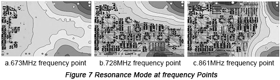
Coupled with Figure 1, it can be observed that several frequency points with relatively large impedance are compatible with frequency points at which resonance is generated. Therefore, with the result of resonance analysis, it can be concluded that in the area with serious resonance decoupling capacitors with suitable capacitance should be placed in order to reduce impedance.
Take frequency point of 673MHz as an example, decoupling capacitors can be placed in parallel so that resonance will be found lost and the corresponding impedance will be prohibited, as is shown in Figure 8.
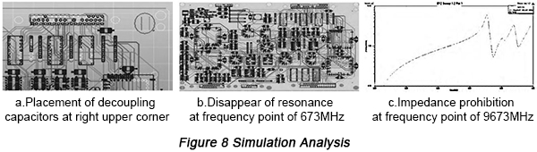
Based on PCB resonance analysis, corresponding positions at which resonance takes place can be determined, based on which capacitors with suitable size are placed in parallel in order to prohibit impedance.


