As the commonest components integrated platform, multi-layer PCBs connect circuit boards and components together. With electronic products becoming light, thin and small in size, and having high performance, IC components have become highly integrated, leading to the high integrity of PCBs. As a result, heat production has obviously increased and thermal density of PCBs has increasingly gone up especially because of the mass utilization of high-frequency IC components such as A/D or D/A type and moving up of circuit frequency. If massive thermal loss fails to be sent out, the reliability of electronic equipment will be greatly influenced. According to statistics, among the elements leading to the failure of electronic equipment, temperature accounts for as high as 55%, as the top cause. With the temperature increasing, the failure rate of electronic components will increase exponentially. Once the environment temperature increases by 10°C, the failure rate of some electronic components can increase to twice large. For aerospace products, this type of thermal control design can't even be ignored as the inappropriate design method for the all kinds of circuits in special environment will possibly result in the complete failure of the whole system. Therefore, much attention must be paid to thermal design during PCB design.
The analysis should commence with the cause analysis. The direct cause of high temperature of PCBs lie in the existence of power consumption components. Each component has power consumption in different extent that arouses the change of thermal strength. There exist 2 types of temperature increase phenomena: local temperature rising or large area temperature rising and short-term temperature rising or long-term temperature rising. Heat transfer has 3 ways: heat conduction, heat convection and heat radiation. Radiation dissipates heat through electromagnetic wave motion passing through space. Since the radiation dissipation features a relatively low amount of heat, it is usually regarded as an assisted dissipation method. This passage will introduce a solution to PCB heat dissipation in the process of long-term operation in the environment with high temperature based on the heat conduction and heat sink transient heat storage technology with a type of servo PCB as an example.
On this servo PCB, there are 2 power amplifier chips with a power of 2W, 2 R/D conversion chips, 2 CPU chips, 1 EPLD chip and 1 A/D conversion chip. The overall power of this servo PCB is 9W. The servo PCB is installed in an airtight environment with limited air convection. Besides, because of the limited space, cold plate dissipation can't be installed on the servo PCB. In order to ensure the normal operation of servo PCB, only heat conduction and heat sink transient heat storage technology can be utilized to transfer the heat produced from the PCB to the body.
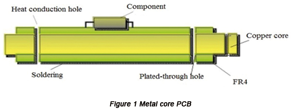
It is a common method to dissipate heat through metal core PCB. First, a metal board with excellent heat conduction is embedded between a multi-layer PCB. Then, heat is dissipated directly from metal board or disjunctive equipment is connected to the metal board to dissipate heat. The operating structure is shown in Figure 1.

The main material of metal core PCB covers aluminum, copper and steel. It can be also used as the ground layer. The upper layer and lower layer of metal core PCB can be interconnected through plated through hole and heat can be transferred on the inner layer and surface of metal core PCB. Heating elements can be directly soldered on the board through the bottom and heat conduction hole. As a result, the heat generated by heating elements is directly transferred to metal core PCB that transmits the heat to the tangent chassis by the heat conduction hole and sends it out. PCBs with such a structure have a wide series of applications but they can also arouse some problems. Metal core PCBs are so thick that deformation tends to take place in the uneven heat dissipation, leading to the loose contact between chips on PCBs and pins. It's easy and quick for metal core PCBs to dissipate heat, which brings about enormous difficulties to chip changing and in the process of chip changing; the local heat attraction of metal core PCBs will lead to the serious deformation of PCBs. It is verified that the larger area a PCB has, the more easily it is deformed.
In order to get the problems above solved, upgrading design must be done to metal core PCBs:
a. 4-layer copper foil with thickness of 0.15mm can be nipped in PCBs so that the thickness of PCBs can increase by 3mm in order to ensure that PCBs aren't deformed easily and the through-hole reliability rises.
b. As to chips with heat generation of 2W, SMT pad can be added to the bottom of chips to transfer the heat to the metal layer of PCB.
c. The chip bottom is capable of transferring heat to the internal copper foil layer by the copper foil with a large area and heat conduction through hole.
d. The insulating layer on both sides of PCB can be milled off to realize the PCB edge metallization. Heat dissipation can be achieved through the contact between bare edge PCB and base. The installation can be finished by 36 screws to increase the heat conduction of PCB and the body.
After the implementation of the measures mentioned above, the upgraded PCB design is shown in Figure 2.


