PADS is a PCB design package developed by Mentor Graphics. It comes in three trim levels (Standard, Standard Plus and Professional), and is considered as a high end commercial grade software package. It has a number of high end features, including signal integrity analysis functions, an advance auto-router, thermal design consideration analysis and support for various project management functions.
Three different versions of PADS have different capabilities and are set for different target users. The table below shows the comparison between them. In this tutorial, PADS Standard is used as an example to display some quick starts.
|
Version
|
Target Users
|
Capabilities
|
|
PADS Standard
|
Engineers focusing primarily
on schematic and PCB design
|
• Detailed design documentation with searchable
PDF output generation;
• Quickly create custom, IPC-compliant land
patterns
;
• Component part selection and instantiation
;
• Powerful search and filtering;
|
|
PADS Standard Plus
|
Hardware engineers who also
require the benefits of analysis
and verification
|
• Signal integrity with crosstalk using HyperLynx®
technology
;
• Integrated constraint management and routing
;
• Thermal and analog simulation
;
• Centralized library;
|
|
PADS Professional
|
The independent, multi-
discipline hardware engineer
who does it all
|
• Self-contained, integrated design flow in one
product for hardware engineers or workgroups
;
• Fewer design spins with virtual prototyping
including SI, PI, Thermal, DFM and 3D validation
;
• Reduced design time through highly integrated
capture, constraints, analysis and layout;
• Easy to deploy, learn and use by both
infrequent and expert users
;
• Effective solution for complex PCB and FPGA
systems design
;
• Constraint-driven, correct by construction
;
• Scalable as your needs grow;
• Low infrastructure overhead
;
|
1. Schematic Capture
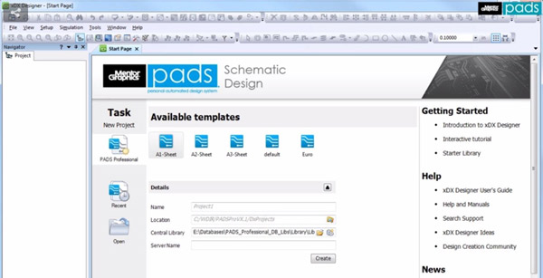
On the start page of PADS, click the Create button to start a schematic capture.
Then, you can set the features of the selected parts. There will be a sample part shown in the right column.
The tool bar on the top of the page provides different types of tools and displays in a circuit. You can make selections of them in your custom circuit design according to your needs.
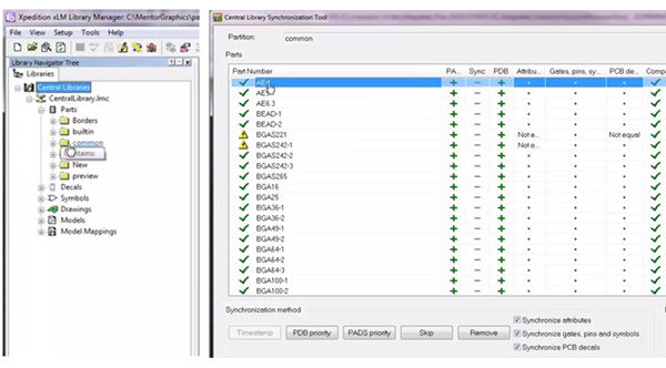
After schematic capture, you can test whether the design of the whole circuit works well. Under the label of Libraries, click Common and then choose the Central Library Synchronization Tool and you can see which part of the circuit has problems. Those parts with yellow warnings indicate their problems.
2. Component Management
With PADS component management, you have access to all component information from a single spreadsheet, without concern for data redundancy, multiple libraries, or time-consuming tool overhead. PADS easily integrates with corporate component and MRP databases through industry-standard ODBC (Open Database Connectivity), enabling geographically dispersed design teams to access central component information. Additionally, databases are kept in sync and up-to-date, thus avoiding costly redesigns and quality problems that otherwise might be undetected until late in the design cycle.
You can use PADS component management in several ways. To find a unique component, simply enter a search criterion (e.g., an 8-bit register) and PADS will display all the available parts that meet the specific criteria. Narrow the search by entering other parameters (e.g., tri-state output) to filter the results. After each search, PADS will display the number of candidates that meet the specified criteria.
To review and select a part, view all candidate parts and their properties in component management spreadsheet. Direct links in the spreadsheet open component datasheets, putting detailed part info at your fingertips. Once selected, it's easy to instantiate the desired component directly onto the schematic.
You can also add a generic component to a schematic.
When it is time to select the PCB manufacturer, simply select the component and PADS will display the available manufacturers and display the availability of manufacturers and parts automatically. The decision can be based on criteria such as lead time, price, or inventory level. Once the selection is made, the component's unique properties can be annotated to the generic component in the schematic.
PADS can also be used to verify the integrity of your entire circuit design, ensuring all information on schematic is consistent with the corporate database. PADS component management also advises which parts of your design haven't been identified uniquely and then annotates missing property information automatically.
With PADS you can search for a specific reuse block or search for reuse blocks that meet a set of criteria. This makes it easy to find and incorporate the right reusable design in a new schematic.
3. PCB Layout
Use PADS powerful layout capabilities to design advanced circuit boards quickly and easily, regardless of their circuitry: high-speed, analog and/or digital, or RF. No matter the complexity of your design, PADS can handle every step of the design process with efficiency and ease.
Get your design done faster with powerful physical design reuse, easy-to-use manufacturing prep, and advanced 3D layout. With full cross-probing between the schematic and layout, PADS will help you get your work done faster, with fewer re-spins and a better finished product. PADS Standard Plus also offers advanced options for chip-on-board/IC packaging support, time-saving Design for Test (DFT) audits, and high-speed auto-routing.
PADS layout is in all PADS configurations, including PADS Professional where it is dual-licensed with advanced technologies from Xpedition® PCB.
Full 3D visualization of the PCB includes components, pads, traces, vias, planes, silkscreen, soldermask, etc. This photorealistic view allows accurate inspections of the board prior to manufacture so that you can check for problems in the design. 3D viewing also provides a direct view of the board's internal layer stackup, giving you all the information needed to design custom PCB knowledgeably and with confidence.
You can also measure distance and object-to-object minimum distance to check how close or far you are from objects based on the constraints you set. You can also import covers, chassis, heatsinks, or other plug-in boards and other mechanical elements into PADS and check if they mate correctly.

Functions introduced in this passage are just some fundamental ones in the use of PADS software in terms of PCB design. More practical functions and excellent performance will be discovered as long as you make use of it in your design work.
Ready for a quick PCB Prototyping or Mass PCB Production? PCBCart is Here to Help!


