Chip mounters, or chip shooters play a critical role in determining automation degree and manufacturing efficiency of SMT (Surface Mount Technology) assembly line. Because mounting efficiency of mounters is closely related with manufacturing efficiency of SMT assembly line, it's authentically necessary and useful to increase mounting efficiency of chip mounters. Improvement in terms of mounting efficiency of mounters depends on a series of issues solutions such as position allocation of component feeder bases and components mounting sequence etc. Focusing on a chip mounter, SM421, a widely-used multi-head gantry-type mounter, this article will explore position allocation of component feeders and mounting sequence so that some optimization methods will be provided concerning mounting techniques.
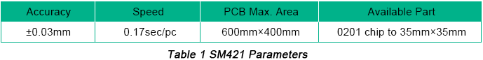
As a chip mounter with a medium mounting speed, SM421 applies a group of 6 mounting heads and its component feeder station can hold at most 120 types of component packages. The specific parameters of SM421 mounter can be summarized into the following table:
Its running process contains the following stages:
a. SMB (Surface Mount Board) is transmitted by conveyor belt to corresponding position and gets fixed;
b. Mounting head selects appropriate nozzle based on component type to be picked;
c. Mounting head moves to the corresponding position where component feeder base is located and nozzle picks components;
d. After being recognized by component visual image, components will be placed at regulated positions on SMB;
e. Steps from b to d are duplicated until component mounting is finished;
f. SMB is transmitted to the next stage by conveyor belt.
Elements Affecting Mounting Efficiency of SM421
Accordingly to analysis on SM421 structure and running process, leading elements affecting mounting efficiency include:
• Moving Speed of Mount Head
Prior to its normal running, moving speed of mount head of SM421 should be preset, indicating the moving speed of mount heads between ambient devices. The speed is determined based on some factors including component package, size and quality. Component size is inversely proportional to the moving speed of mount head in order to stop component displacement due to nozzle changes or component falling off from nozzle due to insufficient vacuum-sorbing force. That's why moving speed of mount head should be controlled. Acceleration or deceleration is demanded in the process of component picking and placing and the extent is also determined by component package, which also needs presetting.
• Position and Account of Component Feeders
Multi-head gantry-type mounters need to get mount head first moved to the corresponding position of component feeder base to absorb components to be mounted and get it moved to mounting position for real mounting in the mounting procedure. Distance between component feeder position and mounting position has extraordinary influence on mounting time. Furthermore, SMD (Surface Mount Devices) type and mounting amount also influences component feeder placement and number of feeders. Apparently, when it comes to SMBs demanding relatively large components mounting, reasonable position of feeder base is especially critical. Furthermore, components should be evenly absorbed by 6 nozzles by mounting heads in each mounting cycle so that mounting cycle times can be minimized with times of nozzle change reduction and mounting efficiency rising.
• Component Mounting Sequence
Each component features its own coordinate on SMB and mounting heads have to go over a complicated path after mounting. Based on different coordinates of components, appropriate component mounting sequence can optimize movement path of mounting heads, which will to some extent reduce movement distance of mounting heads on X-Y axis. As a result, unit mounting time on SMB can be saved so that mounting efficiency of multi-head gantry-type mounter can be improved.
• Role of Nozzles
Appropriate nozzle should be picked up by mounting heads compatible with component type that are ready to be mounted. The mounting time of the whole SMB is directly related with the distance between nozzle placement and component feeder. Plus, some properties owned by nozzles themselves such as insufficient vacuum pressure will possibly lead nozzles to perform badly in terms of adsorption, which may result in repeated adsorptions or even failure in component adsorption. Optimization of nozzle types applied by components is beneficial to nozzle change time reduction and stops nozzles from being frequently changed so that mounting efficiency can be increased.
• Influence of Visual System
Prior to authentic chip mounting, SMDs to be mounted should be recognized by visual system belonging to mounters with images generated in order to ensure that components feature high quality and their packages and sizes are compatible with component data stored in database in accordance with design files. The whole process comprises the following steps: image accumulation, processing and result return. Time that'll be spent on image recognition is determined by quality of algorithm. When components fail to be recognized by the system, mounting failure will be caused and components will be abandoned by mounting head. Once a certain number of components have been abandoned, an alarm will be given by the mounter, after which chip mounter will automatically get powered off.
Taking elements discussed above and practical situation of SM421 into consideration, optimizations can be made through adjusting sequence and number of component feeders, component mounting sequence etc. so that mounting time can be shrinked with mounting efficiency improved.
Mounting Technology Optimization with SM421
• Determination of Component Feeder Position on Feeder Base
Allocation of component feeders on feeder base is regarded as one of the most significant elements affecting mounting efficiency. For a given component placement sequence, appropriate feeder position will drive the movement total run between mounting head's absorption and mounting to be minimum with frequent nozzle change avoided.
The following measures can be made for optimization:
a. Based on rules of min distance to SMB center and max number of components, the first component placement should be determined on feeder base.
b. Optimal route should be followed on mounting path of this type of components.
c. After successful mounting of components in the first feeder, components with the same type should be selected with minimum distance to the last component in the first feeder. This type of components should be arranged in a sequence from left to right close to ambient components. Step b is used as a reference to design the mounting path.
d. Step 2 and 3 are repeated until all the components have been appropriately placed on feeder base.
• Algorithm of Optimal Path of Component Mounting
Travelling Salesman Problem (TSP) is a typical combination problem that is widely applied in fields of military, geographical information and project planning. Besides, it also can be used to solve lots of practical problems such as road traffic management, logistics planning and product production arrangement. In this article, TSP will be used to provide an optimal path in terms of component mounting.
Based on the structure of SM421 and mounting running procedure of mounters that has been discussed in previous part of this article, a TSP math model can be established to optimize component mounting. Suppose an SMB contains a certain number (N) of components to be mounted {C1, C2, C3…CN} while dab indicates the distance between the mounting position of Ca and feeder base of Cb. An integer variant is defined as Kab. When Kab is equal to 1, it demonstrates that it can be achieved to move from Ca component to feeder base of Cb. Otherwise, the value of Kab is zero. Mathematics models established based on TSP include:
① 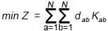
② 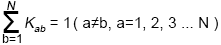
③ 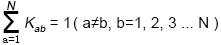
④ 
Among these models, ui indicates sequence of mounted components (i=1, 2, 3…N) and it can be continuously changed. Formula ① is defined as the minimum path of component mounting; Formula ② indicates component Ca features one time mounting; Formula ③ indicates component Cb features one time mounting. As a result, Formula ② and ③ ensure each component features one time mounting.
TSP contains many optimization solution algorithms. One type belongs to traditional algorithms that can be further classified into exact algorithms and approximate optimum algorithms. The other type belongs to digital algorithms, including simulated annealing algorithms, ant colony algorithms and genetic algorithms. In the rest of this article, ant colony algorithms are applied.
Component mounting path optimization can be achieved through optimized ant colony algorithms with the following design considerations:
a. One dimensional array and a pheromone one-dimensional array are set with aim to save the distance between last component's mounting position on board and next component's feeder. Initial value of pheromone is set to be 1.
b. The first ant sets off randomly from a certain component's mounting position and finds the next component's feeder position according to state transition probability. Then it moves to the mounting position and finds the next component's feeder position through the same method until all components finish being mounted.
c. The second ant searches all components' mounting path based on Step b until all ants finish searching for the mounting positions of all components.
d. Pheromone is updated with searching time once added and the optimal path should be saved.
e. All ants conform to Step a to Step d to search for the second time with optimum path saved.
f. Compare two optimal paths and select the better one.
g. Recycling is then implemented based on set searching times with the end optimal path output.
Practical Application in Projects
The experiment is carried out in SMT assembly factory belonging to PCBCart and 15 types of PCBs are selected as subjects. Those boards go through assembly through the software of optimized ant colony algorithms and software owned by SM421 chip mounter with their results compared. The comparison between them can be summarized in Table 2 below.
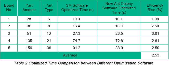
Based on this table, we can conclude that less time is spent on component mounting with software using optimized ant colony algorithms with mounting efficiency rising by 2.53%. Rationality and validity of this method has been fully testified.
With SM421 chip mounter as a research object, this article analyzes elements affecting mounting efficiency of chip mounter, explores mounting technique optimized math models and solves mounting technique optimization issues through the application of optimized ant colony algorithms. Therefore, the application of optimized ant colony algorithms leads to improved mounting efficiency, bring benefits in terms of cost and reliability.


