PCBA, short for printed circuit board assembly, refers to the combination of PCB, components and electronic accessories. Simply speaking, PCBA is actually the PCB with components assembled. This article provides a comprehensive introduction of PCBA from which everybody will learn much.
Assembly Types of PCBA
The main assembly types of PCBA are shown in Table 1 below.
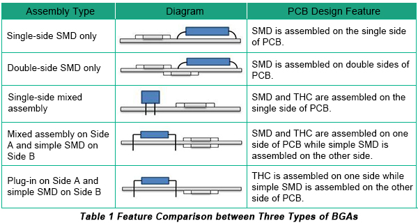
Up to now, single-side SMD only and double-side SMD only are mainly applied for power panel and communication backplane while the other assembly types are applied for complicated devices such as computers, DVDs, mobile phones etc.
SMT Procedure
SMT procedure belongs to a type of solder craft during which paste solder that is distributed to PCB pad in advance is melted through reflow oven so that mechanical and electric connection is implemented between soldering points or pins of SMDs and PCB pad. It is suitable for the soldering of all types of SMDs. The major steps of SMT include tin paste printing, components mounting and reflow soldering.
• Solder paste printing station
This station mainly consists of solder paste, model and solder paste printer. Solder paste is first printed on the corresponding position of PCBs from professional solder paste model through solder paste printer. Then electronic components soldering is finished through components mounting and reflow soldering.

• Components mounting station
This station mainly consists of SMDs, loader and mounter. SMDs are mounted on the certain position of PCBs through component loader and professional mounting software program and are soldered through reflow. Mounters are classified into high-speed mounter and general mounter. The former is applied for crystal chip and small components mounting while the latter for ICs, irregular and large components mounting.

• Reflow soldering station
This station mainly consists of reflow oven. The soldering of SMDs is to make PCBs with components mounted on them pass reflow oven with soldering parameters set to implement components soldering. Reflow oven mainly includes infrared heating and hot wind heating.

Wave soldering procedure
In the process of wave solding, melted solder is transformed into required solder wave through mechanical bump or electromagnetic bump that features jet flow. Then PCBs with components assembled have to pass through solder wave so that mechanical and electric soldering between component soldering points or PCB pad.
The key steps of wave soldering contain component molding, component plug in or mounting, soldering and cooling through solder wave. It means that molded components are plugged on PCB based on requirement. Then PCB loaded with components is pushed into wave soldering system by transmission device. Next solder flux is sprayed and PCB will suffer preheating in the preheating zone. The final step comes with the wave soldering and cooling.
• Components molding and plug-in components
The main job of this station is to premold some components in order to make them meet the requirements of mounting, plugging and wave soldering.

• Wave soldering
The main job of wave soldering is to plug molded components on the required places according to some requirements. Then PCB loaded with components enters wave soldering system by transmission device. Soldering flux is first sprayed and PCB suffers preheating in the preheating zone. Next comes wave soldering with cooling as the final step.

Basics on Soldering
Soldering can be classified into the following three categories: fusion welding, pressure welding and brazing that are displayed in Figure 3.

Besides, soldering has other categories such as ultrasonic pressure welding, gold ball bonding and laser soldering.
Brazing can be also classified into hard brazing and soft brazing. The former refers to high temperature and large scale soldering while the latter refers to relatively low temperature and small scale soldering such as component soldering. Concerning some aspects on soft brazing, the following content is complemented.
a. Definition: Soft brazing refers to the soldering with a temperature that is lower than 450°C.
b. Features: The following figure indicates features of soft brazing.

c. Basic theory
When metal is being soldered and the soldered metal is heated to the certain temperature range, the oxide layer and contaminant will be cleaned under the activation of welding flux and metal surface will obtain sufficient activation energy. Melting solder is melted, wetted, expanded and connected with metallurgy. As weld occurs between solder and soldered metal surface, solder will become solid after cooling with soldering points formed. Strength of extension is related with lattice structure and thickness of bonding layer between metal.
d. Brazing procedure: The main procedure of soft brazing includes wetting, diffusion, dissolution and metallurgic bonding.
In conclusion, understanding the intricacies of the Printed Circuit Board Assembly (PCBA) is key to realizing the quality and reliability of electronic devices. From the delineation of PCBA as the integration of PCBs with accessories and components to the explanation of the SMT and wave soldering process, this comprehensive explanation identifies the steps involved in the assembly process. Each step, from solder paste printing and component mounting to reflow and wave soldering, is vital to creating robust connections that offer both mechanical stability and electrical functionality. By streamlining these processes, manufacturers are capable of constructing complex devices, from cell phones to communication backplanes, with efficiency and precision.
For those looking to optimize their PCBA processes or embark on new electronic projects, consider leveraging the expertise and resources of PCBCart. With their extensive range of assembly services, including both SMT and wave soldering, and adherence to strict quality standards, PCBCart ensures your designs are brought to life with exceptional accuracy. Reach out to PCBCart today for a quote on PCB Assembly and experience the benefits of working with a leader in the industry dedicated to meeting your specific needs and timelines.
Quick PCB Assembly Quote Available—Request Now
Helpful Resources
• Advanced PCB Assembly Capabilities Meeting All of Your Electronic Assembly Demands
• PCB Design File Requirements for Quick PCB Assembly Quote and Production
• Instruction on Getting Free PCB Assembly Quotes
• PCB Design Tips to Better Take Advantage of PCBCart's Assembly Capabilities And Save Cost
• Printed Circuit Boards Assembly (PCBA) Process | PCBCart


