



A coin-cell industrial sensor, such as an asset tracker, a vibration node or an environmental monitor, has a fixed energy budget. Firmware and component selection determine how that budget is spent, but assembly quality determines how much of it leaks away before the sensor does any useful work. This article explains the assembly-side factors that matter most for battery-powered sensor boards built on primary (non-rechargeable) cells.
Scope: stationary industrial wireless sensors powered by coin cells or primary lithium batteries.
Why Does Assembly Quality Affect Battery Life?
On a mains-powered board, a residue-related leakage path of a few hundred nanoamps is negligible. On a sensor designed for a 10-year service life, the same path can consume a significant share of the total energy budget.
An Illustrative Power Budget
The following figures are illustrative calculations, not measured data:
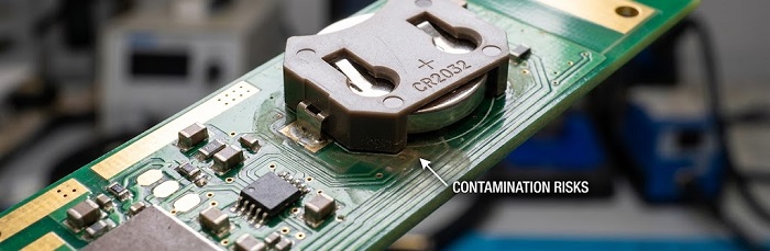
Major cell manufacturers rate the CR2032 at roughly 220–240 mAh nominal capacity at low drain. We use 230 mAh here.
Spread over 10 years (about 87,600 hours), 230 mAh allows an average current of about 2.6 µA, before self-discharge and pulse-load derating are taken into account.
A contamination-induced leakage path of 10 MΩ across a 3.0 V rail draws 0.3 µA, or about 11% of that budget.
At 1 MΩ, the leakage current reaches 3 µA, which exceeds the entire average budget. The sensor will then miss its target life regardless of how efficient its firmware is.
Surface insulation resistance in this range is rarely detected by a room-temperature functional test. It usually appears only after the board is exposed to humidity in the field.
Circuits Most Sensitive to Residue
High-impedance voltage dividers (often 1–10 MΩ) used for battery monitoring. Leakage drains current and also distorts the measured value.
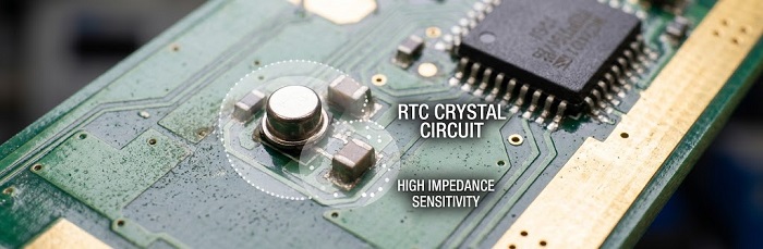
32.768 kHz RTC crystal circuits. These operate at very low drive levels with load capacitances of only a few picofarads. MCU vendors’ oscillator design application notes warn that residue and humidity can add parasitic capacitance and leakage, which may cause frequency drift or start-up failure.
Sensor analog front ends with picoamp-level input bias currents.
Power-gating MOSFET gates and wake-up comparator inputs. Leakage at these nodes can keep a power domain partially switched on.
No-Clean Solder Paste: Why It Is the Default and Where It Can Fail
No-clean solder paste is usually the preferred choice for battery-powered sensor boards, for three reasons:
Water-soluble fluxes leave highly active residues if washing is incomplete, and washing under low-standoff parts such as QFNs and LGA modules is difficult to verify.
Many sensor boards carry components that should not be washed, such as MEMS sensors with vent holes and humidity sensors with exposed membranes.
When fully reflowed, no-clean residue is encapsulated and has low conductivity.
The important qualifier is fully reflowed. No-clean residue is benign only when its activators have been consumed or thermally decomposed. There are two common failure modes:
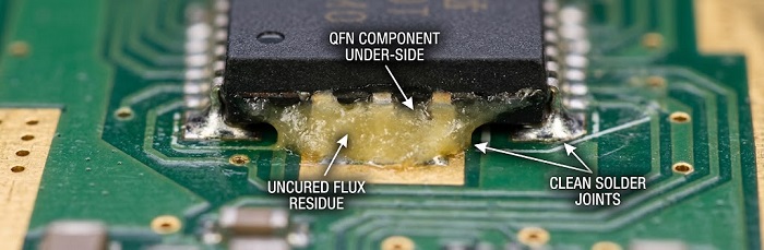
Flux trapped under low-standoff components. Flux under a QFN or a shielded RF module may not reach full activation temperature, leaving active weak organic acids behind.
Flux spread from secondary soldering. Liquid flux from wave soldering or hand soldering can migrate into SMT areas that never receive enough heat to neutralize it.
The following process measures reduce these risks:
Flux classification. Specify a low-activity flux under IPC J-STD-004. ROL0 or REL0, with halide content below 0.05%, is a common choice for high-impedance designs.
Deposit control. Paste volume should be kept tightly controlled, because excess paste means excess flux. Our MYCRONIC jet printer/dispenser deposits paste pad by pad on fine-pitch and mixed-size layouts, and 3D SPI verifies deposit volume before placement.
Reflow profile. The profile on our JTR-1200D-N reflow oven should be set to achieve complete flux activation as well as sound joint formation.
No partial cleaning. Spot-cleaning no-clean residue with IPA can dissolve the protective resin and spread the activators over a wider area. A board should either be fully cleaned with a validated process or left as soldered.
ROSE Testing: What It Shows and What It Misses
ROSE (Resistivity of Solvent Extract) testing, defined in IPC-TM-650 2.3.25, extracts ionic residue from the whole assembly and reports it as an NaCl-equivalent value per unit area.
What ROSE does well:
It detects gross process drift, such as a paste lot change or contamination introduced during handling.
It supports lot-to-lot trend monitoring once a baseline has been established for a specific board and process.
What ROSE misses:
The widely quoted limit of 1.56 µg/cm² NaCl equivalent originates in 1970s military specifications. Since Revision G Amendment 1, IPC J-STD-001 no longer treats it as a universal pass/fail limit. Instead, it requires objective evidence that residue levels are acceptable for the specific product and process.
ROSE averages over the entire board, so a concentrated residue pocket under a single QFN next to a 10 MΩ divider can be diluted below the detection threshold.
Some weak organic acids in no-clean residue dissolve poorly in standard ROSE test solutions.
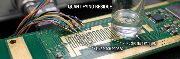
For leakage-critical designs, OEMs often add ion chromatography (IPC-TM-650 2.3.28) or surface insulation resistance testing (IPC-TM-650 2.6.3.7) on a representative test vehicle to their qualification plans. These tests are frequently performed by independent laboratories. Define the test method and acceptance criteria in your build documentation so that they can be reviewed at the quotation stage.
Battery Holders and Connectors: THT Soldering Considerations
Most industrial sensors use through-hole coin-cell holders or battery connectors, because these provide reliable mechanical retention under vibration. Their solder joints present specific challenges.
Thermal Mass and Hole Fill
Battery holder contacts are often made from thick nickel-plated steel with high thermal mass. If heat input is insufficient, the result can be cold joints and incomplete barrel fill. For Class 2 and Class 3 plated through-holes, IPC-A-610 generally requires at least 75% vertical fill, with limited exceptions.
Our automated selective wave soldering system (ZSWHPS-11-2, with nitrogen protection) addresses both heat input and flux residue:
Per-joint settings. Preheat and dwell time are set for each joint, so high-mass battery contacts receive enough heat without overheating nearby SMT components.
Nitrogen protection. The nitrogen atmosphere reduces oxidation at the solder interface and improves wetting on plated contacts.
Localized fluxing. Flux is applied only to the selected joints rather than across the whole bottom side, which limits the residue-spread risk described above.
Plastic Housing Limits
Many holders have plastic housings with limited heat resistance. Soldering parameters should therefore be checked against the holder manufacturer’s soldering specification, not only against the board’s general profile.
Inspection
3D AOI measures fillet height, lead protrusion, bridging and holder tilt. Holder tilt is a common cause of intermittent cell contact.
Off-line X-ray can be used to check barrel fill on battery contacts. AOI cannot see inside the hole, so this is the method for verifying fill.
Closed-loop inspection. Our 3D SPI and 3D AOI systems work as a closed loop, so inspection results feed back into the paste process and the same defect does not repeat across a lot.
Traceability
Our Smart MES with UID traceability and laser marking links each serialized board to its material lots and process records. If field units show shortened battery life, these records help narrow the investigation to a specific lot or process window.
DFM Recommendations for Low-Power Sensor Boards
Isolate high-impedance nodes. Provide adequate spacing around MΩ-range dividers and crystal pins, and add a guard ring where the design allows.
Separate THT joints from sensitive circuits. Position battery holders and other through-hole parts away from RTC crystals and high-impedance dividers.
Specify the flux class on the assembly drawing, for example “no-clean, J-STD-004 ROL0 or REL0,” rather than “no-clean” alone.
Define cleanliness requirements by method. State which test is used for lot monitoring and which for process qualification.
Choose holders suited to selective soldering. Look for adequate lead-to-hole clearance and housings rated for the required soldering temperature.
State the IPC-A-610 class that applies to battery contact joints.
Define when the cell is installed. If cells are to be fitted after delivery, state this in the assembly documentation so the holder is not loaded during assembly.
Submit Your Sensor PCBA Project
PCBCart builds high-mix, low-volume PCBA for industrial customers under an IATF 16949-certified quality system. Send us your Gerber files, BOM and assembly requirements, and our engineers will review your design for manufacturability before production.
Submit Your Sensor PCBA Project for Evaluation
Helpful Resources
Never Trust “No Clean” Too Much - “No Clean” Flux Cleaning Significance
How to Clean PCBs after Surface Mount Soldering


