In accordance with the development trend of modern electronics products, the primary progress trend of newly-developed electronics products involves miniaturization, 3D assembly and high reliability. The expansion of electronics market leads worldwide PCBs to constantly upgrade in terms of scale and technology. Thereafter, PCB (printed circuit board) manufacturers have been striving to explore numerous technologies compatible with the development trend mentioned above. Due to limitations on environment and applications, flexible PCB design comes into being and to further ensure the solderability and 3D assembly capability of electronics products, flex-rigid PCB was born.
Fabrication technology of rigid-flex PCB maintains constantly upgrading with technology development and increasing advancement of products. As far as key fabrication technology of flex-rigid PCB is concerned, window fabrication is definitely regarded as a core. This article will demonstrate leading window fabrication technologies of flex-rigid PCB, including window opening method, copper foil etching method, filling method, positive and negative depth control method, laser cutting method and resistance adhesive method.
Window Opening Method
Window opening method refers to the process in which rigid-flex PCB with a core board structure takes advantage of mechanical milling or mold punching to eliminate rigid core in flexible portion and no-flow prepreg so that a flex-rigid PCB will be generated through lamination. A 6-layer rigid-flex PCB is used as an example to illuminate window opening method technology and its fabrication process.
• Board Structure
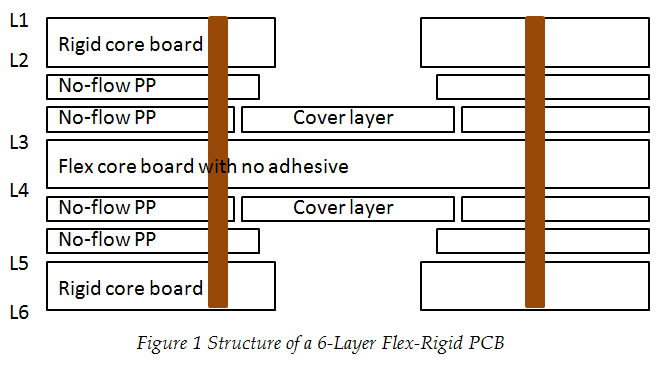
• Fabrication Process
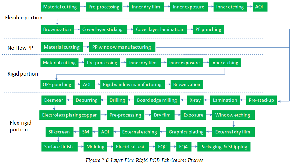
• Key Technology Analysis
a. Cover Layer Coating
X-section analysis is implemented on through blind via after local coating and overall coating, which can be concluded that local coating technology is capable of defeating issues of delamination due to thermal effect and electrical conductivity failure so that product reliability will be improved.
b. PE Punching for Flexible Portion
Because modifications will take place on flexible board size during cover layer lamination, PE punching should be implemented after cover layer manufacturing to improve layer alignment.
c. No-Flow PP Window Manufacturing
Based on IPC-TM-650 test principles and with practical lamination process considered, no-flow PP adhesive overflow amount can be tested in terms of different manufacturers and different piece count. After compensation design is carried out on original window of customers, flatness can be ensured at the interface of flex-rigid PCB.
d. Window Manufacturing at Rigid Portion
Mechanical milling or mold punching should be used to eliminate rigid core compatible with flexible portion. Mold punching works better on mass-volume production while mechanical milling on mid or low-volume production.
Copper Foil Etching Method
Copper foil etching method refers to the process that rigid-flex PCB with a copper foil structure takes advantage of solutions to make the window at flexible portion to be exposed. As far as copper foil etching method is concerned, a 4-layer flex-rigid PCB is used as an example to illuminate copper foil etching method technology and its fabrication process.
• Board Structure
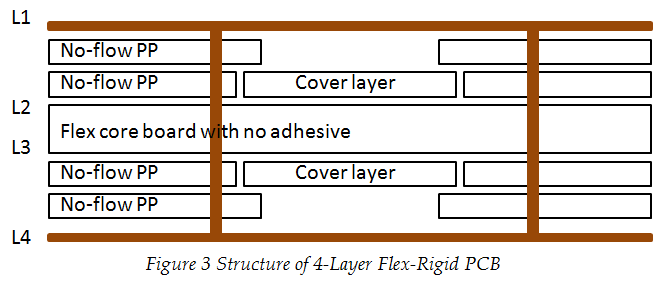
• Fabrication Process
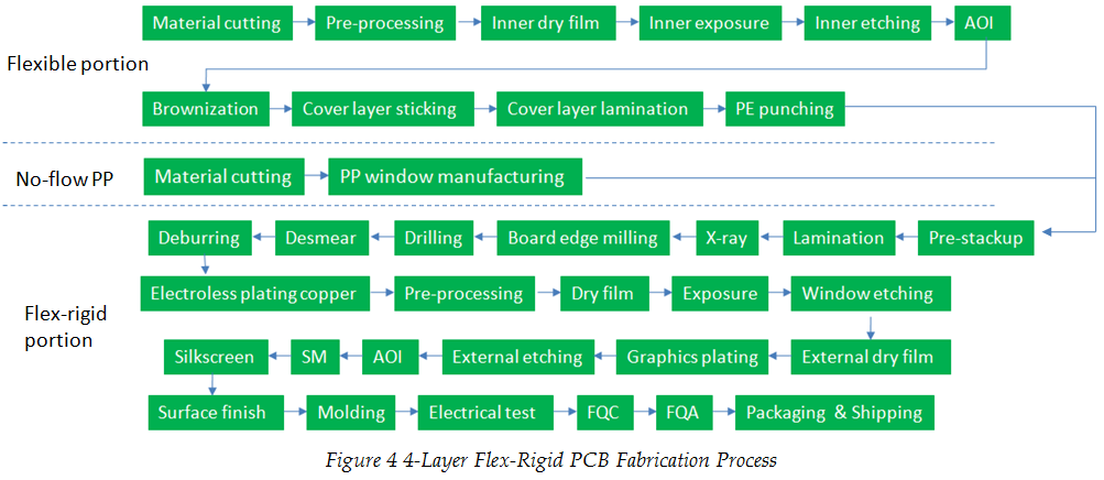
• Key Technology Analysis
a. Lamination
Based on different CTE (coefficient of thermal expansion) for different materials, the implementation of special lamination layout structure makes external copper foil on PCB receive even tensile stress during lamination so that some issues can be defeated including bad PP adhesive filling, copper foil wrinkles and damage and bad flatness of board surface.
b. Window Etching
Negative etching is carried out after electricity running with copper plated board completed and copper foil at flexible portion should be etched away with flexible board exposed.
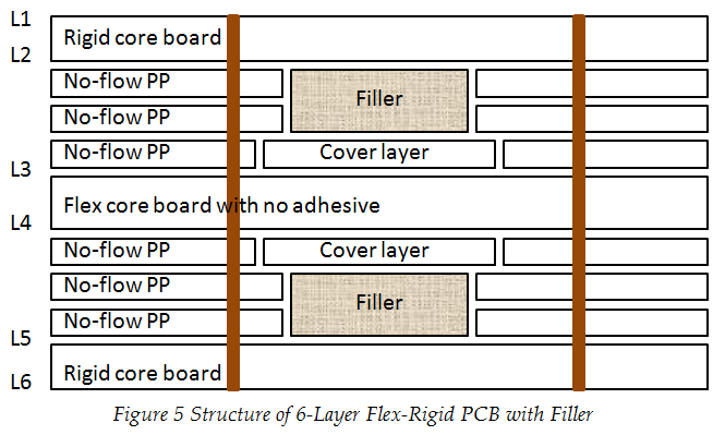
Filling Method
Filling method refers to the process in which fillers are placed at window of flex-rigid PCB and fillers and surface portion will be eliminated through blind milling. For filling method, a 6-layer flex-rigid PCB is used as an example to illuminate filling method technology and its fabrication process.
• Board Structure
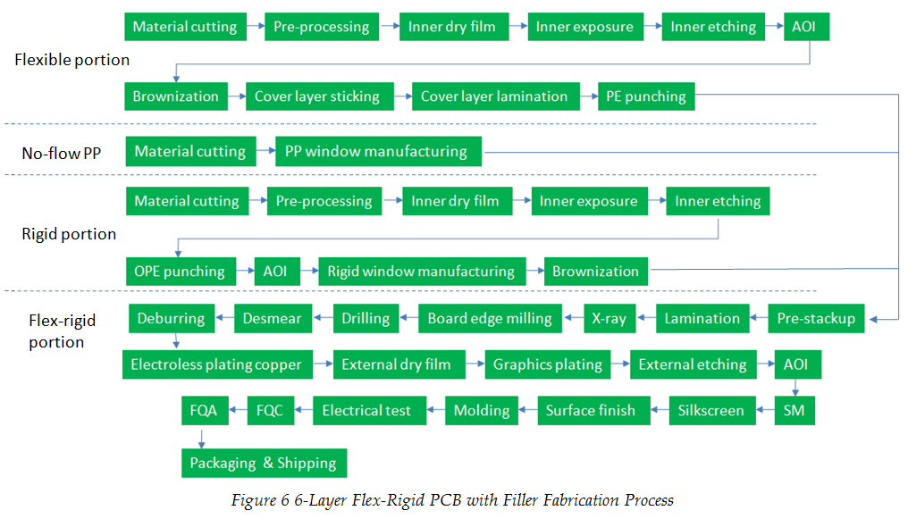
• Fabrication Process
• Key Technology Analysis
a. Pre-stackup
During the process of stackup, filler is placed into hollow window, meeting the following requirement:
① Filler should be soft and smooth in surface;
② Filler should be high temperature resistant and CTE should be equivalent to or lower than substrate material;
③ Figure of filler should be the same as that of window with high stability;
④ Thickness of filler should be equivalent to that of filling.
b. Molding
Window at the disconnected position at flex-rigid PCB is fabricated by applying mechanical milling and window at connected position is fabricated by mechanical depth controlled. As filler is taken out, flexible area will be instantly exposed.
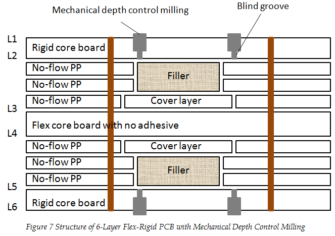
Positive and Negative Depth Control Method
Positive and negative depth control method refers to the process in which a blind groove is in advance manufactured on the rigid board adjacent to flexible board. After stackup and lamination, mechanical depth control method is used to be combined with blind groove during molding. Then, rigid board will be eliminated at window position to make flexible portion exposed. As far as positive and negative depth control method is concerned, a 6-layer flex-rigid PCB is used as an example to illuminate positive and negative depth control method technology and its fabrication process.
• Board Structure
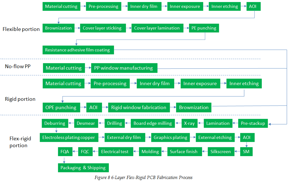
• Fabrication Process
• Key Technology Analysis
a. Blind Groove Fabrication for Rigid Board
The depth of rigid blind groove is usually controlled to be in the range from 1/3 to 2/3 of that of rigid core board and it shouldn't exceed the range of practical mechanical depth control capability in order to stop milling damaging flexible board. blind groove can be manufactured in the following methods:
① Mechanical milling blind groove. Blind groove is manufactured by applying digital-controlled milling machine.
② Blind groove by X-ray. Carbon dioxide x-ray machine is used to fabricate blind groove in connected holes.
③ Blind groove by laser cutting. Blind groove is cut by applying UV laser cutting machine.
④ V-cut blind groove. V-cut blind groove is manufactured by applying V-cut machine.
This article introduces the key technologies of flex-rigid PCB fabrication, that is, window manufacturing and different methods work for different types of rigid-flex PCB. All the methods can be cooperatively applied to contribute to high reliability and excellent performance of flex-rigid PCB.
Reach PCBCart, a China Professional Flex-rigid PCB Production Solution Provider


