


PCB successfully added to your shopping cart
Contrast on Soldering Technologies Used in Lead and Lead-Free Reflow Soldering
MVCs refer to the most vulnerable components (MVCs) during reflow soldering such as liquid dielectric aluminum electrolytic capacitors, connectors, DIP switches, LEDs, transformers, PCB (Printed Circuit Board) substrate material etc. Lead and lead-free components differ from each other in terms of their capability to withstand reflow soldering.
• Lead Components
Because the peak temperature in lead reflow soldering won't exceed 230°C, heat resistance of MVCs should be set to be at 240°C, including all the soldering tools manufactured by industrial manufacturers, soldering equipment and supporting materials used for soldering all of which are designed and selected based on heat resistance of 240°C.
• Lead-Free Components
Peak temperature in lead-free reflow soldering can be as high as 250°C, so the lowest heat resistance of MVCs has to be set to be at least 260°C. As a result, all the soldering tools manufactured by industrial manufacturers, soldering equipment and supporting materials used for soldering have to be designed and selected based on heat resistance of 260°C.
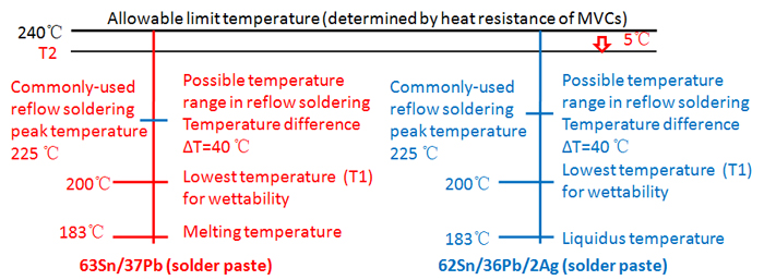
Ingredient of Solder Paste Commonly Used in Reflow Soldering
• Lead Reflow Soldering
Equivalent to lead wave soldering, lead reflow soldering shares the same commonly-used solder paste ingredient, that is, Sn37Pb eutectic solder paste and Sn36Pb2Ag solder paste.
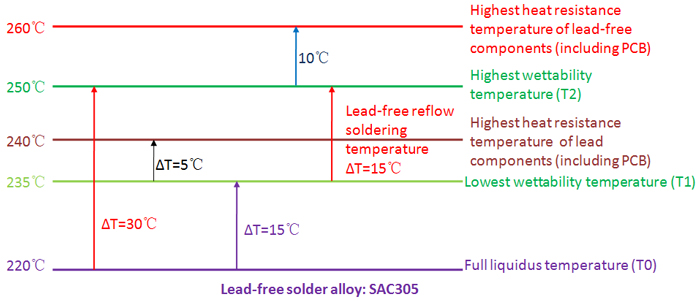
• Lead-Free Reflow Soldering
Ingredient of alloy in solder paste applied for lead-free reflow soldering mainly includes:
a. SAC305 solder paste. As one of the most wide-ranging elements applied in modern industry, it features a melting temperature from 217°C to 220°C.
b. SAC387 solder paste. As eutectic composition of SnAgCu alloy, SAC387 features its melting temperature at 217°C on which it is able to complete solid-liquid transition. Due to its low melting temperature, it's primarily applied in some specialty products, military applications for example.
Reflow Soldering Peak Temperature Range
• Lead Reflow Soldering
As far as simple products are concerned, peak temperature range during lead reflow soldering is from 205°C to 220°C. When it comes to complex products such as some IC packages, however, peak temperature may be as high as 225°C, which is indicated in the figure below.
• Lead-Free Reflow Soldering
As far as lead-free reflow soldering is concerned, if lowest peak temperature is 235°C in practical reflow soldering, the highest peak temperature will be determined by temperature difference (ΔT) on PCB board which, however, is determined by PCB size, PCB board thickness, PCB layer count, component layout, copper layer distribution, component size and thermal capacity. Those large and thick PCBs with large and complex components assembled on feature a typical ΔT that is as high as 20°C to 25°C. As a result, peak temperature should be minimized to prolong preheating and reflow soldering time, as is indicated in the following figure.
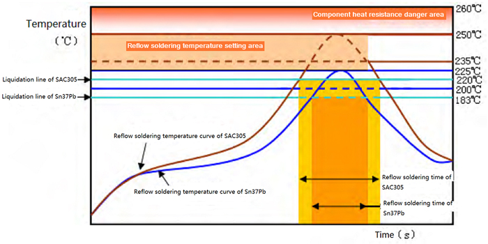
Reflow Soldering Time-Temperature Curve
Time-temperature curve comparison between lead and lead-free reflow soldering is demonstrated in the following figure.
Self-Aligned Capability Comparison between Lead and Lead-Free Reflow Soldering
• Lead Reflow Soldering
When lead solder paste (Sn37Pb, Sn36Pb2Ag) is applied with PCB surface finish being HASL Sn37Pb or OSP, if assembled components deviate from pads by 50%, self-alignment can be well implemented.
• Lead-Free Reflow Soldering
a. As air participates in reflow soldering, SAC305 solder paste is applied with PCB pad surface finish being ENIG and OSP and solder joints SAC305. If assembled components deviate from pads by 25%, self-alignment can be well implemented.
b. As nitrogen participates in reflow soldering, SAC305 solder paste is applied with PCB pad surface finish being ENIG and OSP and solder joints SAC305. If assembled components deviate from pads by 50%, self-alignment can be well implemented as well.
Lead Eliminating Procedure Comparison between Lead and Lead-Free Solder Joints
Rome is not build in one day. Total transition can never be achieved just by one step from complete SnPb soldering system to totally lead-free soldering system. A transient process must be available with lead and lead-free elements coexisting. That's because different apartments in electronics manufacturing industries fail to keep synchronization on lead-free schedule and technology preparation. As a result, soldering defects tend to be caused in this transient process.
• Forward compatibility
For example, when lead-free SAC solder paste is used to solder lead BGA (ball grid array) solder joints, forward compatibility will take place, which derives from the fact that component distributors' lead-free schedule is later than that of PCB manufacturers'. In this situation, BGA solder joints are melted first and covered on solder paste whose alloy isn't melted, leading to massive collapse and oxidation of lead solder balls. As a result, vacancies and internal non-metal slag inclusions will be generated due to difficult expelling of flux solvent and contaminant in solder paste, which are not allowed.
• Backward compatibility
When lead-free solder needs to be cooperated with lead solder paste, backward compatibility will happen. Solder paste (SnPb) coated on pad is melted but SAC solder balls are still not melted. Lead will be dissipated to the boundary of solder ball crystal particles that are not totally melted. How far lead can be dissipated in SAC solder balls depends on how high reflow temperature is set and how soon SnPb solder will be melted in solder paste. As a result, the solder joints are uneven and unstable.
To obtain higher quality and reliability of solder joints, reflow time-temperature curve has to be reset so that SAC solder balls can be completely melted and lead in SnPb solder paste can be absolutely mixed with melted SAC solder balls.
Cooling Rate Comparison between Lead and Lead-Free Reflow Soldering Procedures
• Lead Reflow Soldering
Since the peak temperature of lead reflow soldering is lower than that of lead-free reflow soldering and the accumulated heat by soldered devices is not so high, it's sufficient that the cooling rate of cooling unit maintains a speed at 3 to 4°C/s.
• Lead-Free Reflow Soldering
Because lead-free reflow soldering features a high temperature and accumulates more heat, to stop solder joints from cooling and solidification for long time and crystal particles from becoming thick, accelerating cooling can also hinder segregation. Therefore, cooling equipment of reflow soldering equipment should have a higher cooling rate so that temperature of solder joints can be decreased quickly. Cooling rate is usually required to be at 5 to 6°C/s.
Influence of Cooling Rate on Creep Resistance
• Influence of lead-free solder cooling rate on creep resistance
a. Cooling rate improvement leads devices to creep resistance increasing, which is because fast cooling modifies microstructure. Small dendrite formed by fast cooling and Ag3Sn particles in substrate will strengthen contact break resistance so that solder joints' creep resistance will be improved.
b. Slow cooling leads crystal particles to grow, which tends to cause the generation and expansion of cracks. Creep resistance improvement of SnAg primarily dissipates allocated particles with strengthening function.
• Influence of lead solder cooling rate on creep resistance
Different from SAC alloy, lead will perform as a ball shape when lead eutectic solder goes through fast cooling and all the phases will become refined in the case of accelerating cooling speed. However, the difference lies in the fact that lead features lower hardness than Sn substrate and larger content than Ag in SnAg and SAC alloy.
PCBCart Offers Lead Soldering and Lead-Free Soldering Manufacturing Techniques For PCB Assembly
We understand different projects require different soldering techniques. To meet all demands of clients, we offer both Lead Soldering and Lead-Free Soldering Manufacturing Techniques for printed circuit boards assembly. Want to know how much your PCB Assembly work cost? Click the following button to get a PCBA quote, it does not cost you a penny!
Request PCB Assembly Quote - Lead/Lead-Free Soldering
Helpful Resources
• Full Feature PCB Manufacturing Service
• Advanced PCB Assembly Service with Multiple Value-Added Options
• Lead Free PCB Manufacturing Technology Introduction
• Comparison between Lead Soldering and Lead-Free Soldering Manufacturing Procedure in PCBA
• Contrast on Soldering Technologies Used in Lead and Lead-Free Wave Soldering
• Reliability Comparison between Lead and Lead-Free Solder Joints