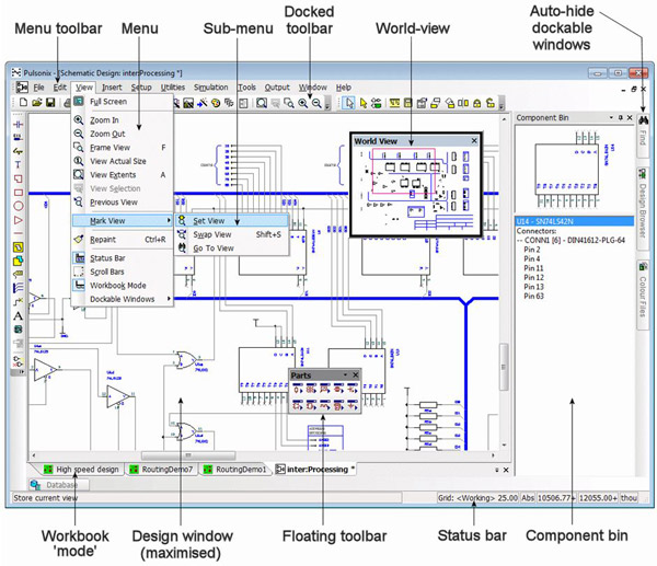
Although Pulsonix is a sophisticated PCB design tool, it has also been constructed to be easy to use. It has been created around the Microsoft Windows style graphical user interface to provide a familiar operating environment.
Launching Pulsonix
After launching Pulsonix, the main application window appears. It operates a multiple document interface (MDI), so you can open any number and combination of different Pulsonix circuit design types, as well as libraries and additional tools.
General Utilities
• Undo & Redo
Pulsonix contains unlimited multi-level Undo and Redo capabilities for use through the product. Undo can be used to reverse the last operations that have been completed. Redo can be used sequentially to undo more than one operation. It can also be a useful and flexible tool to interactively try different iterations of an operation.
Undo and Redo steps are only available back to the maximum number of levels set. Not all operations are available to Undo/Redo, and a list of unavailable operations is listed in the on-line help under Undo.
The number of Undo levels is set up in the Settings menu under the Options function and General tab.

• Moving Items
There are two methods of moving objects in Pulsonix. The first and most widely used is the drag and drop methodology, for use when an interactive move is required. This is modeless in that it can be used without a mode selected. The second method is the Move mode. This can be accessed from the Edit toolbar button and from the context menu. It allows you to move items with the mouse button left up.
• Mirror
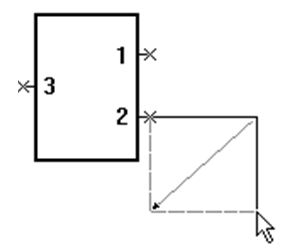
Within Schematics, Mirror will flip a Component or Documentation Symbol using the centre of the symbols bounding box as the axis point. Text in Schematics cannot be mirrored.
When used with connections, Busses and Shapes within Schematics any dynamic segments can be mirrored across to their opposite diagonal point. This applies to any two segments but does not apply to more than two segments or less than two segments.
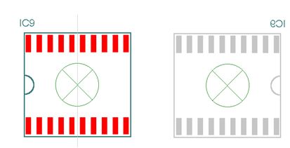
When used in the PCB editor, Mirror has three effects. The first will flip the complete Component, Documentation Symbol and Text to the other side of the design (if the alternative opposite side is available). When surface mounted components (with surface mounted pads defined on a surface layer) the pads will also be mirrored to the other side of the design automatically. The second effect will work on whole design shapes and will mirror the shape on the same layer. The third mode will work on any two dynamic segments.
Components and Documentation Symbols are mirrored around their Component origin axis to maintain their position. The diagram below shows how the Component will look after rotation but has been moved over to the right for clarity. The axis points would actually be coincident once mirrored.
• Rotating Items
Rotate can be used on most items within the design. It is available from the Edit toolbar, using the key as a shortcut, and from the context menu when an item is selected or being moved. Rotate is also available from the Item Properties dialog for some items either single or multiple items of the same type (it is not available for all design item types). This is particularly useful if a number of components are selected for rotation to the same angle, for example.
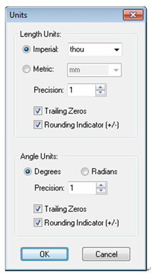
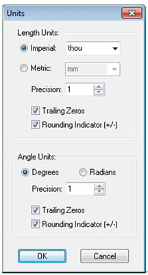
Rotation steps can be defined down to 1/100,000th of a degree, and this level of precision allows accurate rotation of items when using polar/radial grids. The precision and rotation unit type of Degrees or Radians can be defined from the Settings menu under Angle Units on the Units dialog.
Setting Up the Design
• Units
The basic working units can be changed between Imperial and Metric, and between Degress and Radians for angle units. These are the units of the co-ordinates and lengths displayed in the dialogs and edited by you. The Units dialog on the Setup menu is used to define these units and the precision at which they are displayed.
The design units are stored in an internal database with a precision of 1/100 micron regardless of what the unit precision is set to.
• Grids
The Grids dialog allows you to add or change the settings for any of the grids in the design. The grids dialog is available on the Setup menu or by selecting the Grids button on the Grid Step dialog.
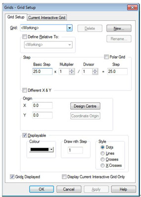
You can define your own grids by first typing in a name using the New button. The grid Step should then be typed in and the Multiplier (and Divided if required). Use the Multiplier and Divider entries to create fractional grids that do not suffer from rounding errors. You can also set its visibility by selecting the Displayable check box. Selecting OK will save the grid and display it (if the zoom level allows it).
You can change the display of the grid to draw any number of grid steps using the Draw nth Step box. This can be useful if the grid is only required every 10 grid points. The Style of the grid can also be changed between Dots, Lines, Crosses and X Crosses. A mix of each is also allowed for different displayed grids but the colours used should be chosen carefully.

Schematic Capture Editor
There are a number of ways of starting a new Schematic within Pulsonix:
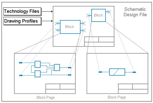
a). Start with the supplied Technology Files and/or Drawing Profile. This is the preferred and recommended method of starting a Pulsonix design.
b). Start with an empty design, namely no Technology files and Drawing Profiles. You can add the necessary styles etc. to the design as you need them.
c). Start by importing a design from another system using the import mechanism. Once the Schematic has been imported, a Technology file can be made from it as can a Drawing Profile, and libraries imported or created from the design.
The discussion below deals with the basic start, with and without Technology files and Drawing Profiles. It then builds the design using the natural design flow as a guide, adding design items as they are required, each topic deals with one feature of the process.
• Starting a New Drawing with Default Files
Regardless of which active window is currently open in Pulsonix, you can start a new Schematic design using the New option. This dialog can also be used for starting new designs (Schematics and PCB), Library items, Technologies, Profiles and access to the Library item creation wizards.
• Adding Components
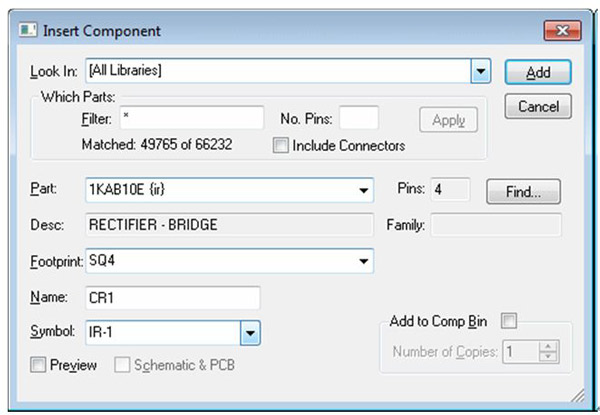
Once the Design Settings have been set and the Drawing Profiles (Page Border) inserted, the Schematic editor is ready for the design to be created. One of the first processes to attempt is the insertion of Symbols into the Schematic design; Pulsonix provides the Insert Component function for this purpose. Part and Symbol contents are created and saved into corresponding libraries. The Part entry contains a Part name, a Footprint (optional if translate to PCB isn't required) and a corresponding Schematic Symbol or multiple symbols if the Part represents a multi-gated Component.
Using Insert Component will allow you to select the required Part from the appropriate library or libraries.
• Adding Connectors
a). Click the Insertmenu, click the Connector Pinoption.
b). Select the Parts library you wish to use using the Look in: drop down list.
c). A list of Connector Part Names will appear in the dialog. Only parts that were added to the library, as connectors will be shown. Use the Filter to reduce this list to the parts that you are interested in.
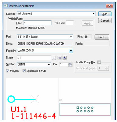
d). Choose which connector part you wish to add from the list of Parts: using the drop down list.
e). Change the pin number you want to add (if the default provided is not suitable) using Pin:
f). Add connector (or a number of its copies) directly to the Component Bin, or add a connector pin interactively into the design using Add button.
g). If adding to the Component Bin, you are returned immediately to the dialog, else follow these next steps.
h). Using the mouse, move the connector pin to the desired position and click to place it into the design.
i). Continue to place connector pins using the same Part. Each pin is auto incremented to the next free pin number in the design, or, if all pins of the Component have been added, the Component's name is auto incremented to the next free name in the design.
j). Press the Esc key, to return to the add connector pin dialog.
PCB Design Editor
• Getting Started with the Design
There are a number of ways to start a new circuit board layout. The way in which you start will depend on, whether you have a Pulsonix Schematic design, a netlist or a sheet of paper with a Schematics design on it:
a). Using Pulsonix Schematic Capture as "front-end" to the PCB system. The nets and components are translated to PCB in an integrated environment.
b). Using a netlist that is derived from another CAE or Schematic system.
c). Using Pulsonix PCB design editor interactively creating the design on the fly. This means without an initial netlist just adding connections and components as you design the PCB.
• Design Setup for PCB Layout
Before getting started in PCB design, you should check that when you start adding design items, the design editor will behave as you expect or require it to.
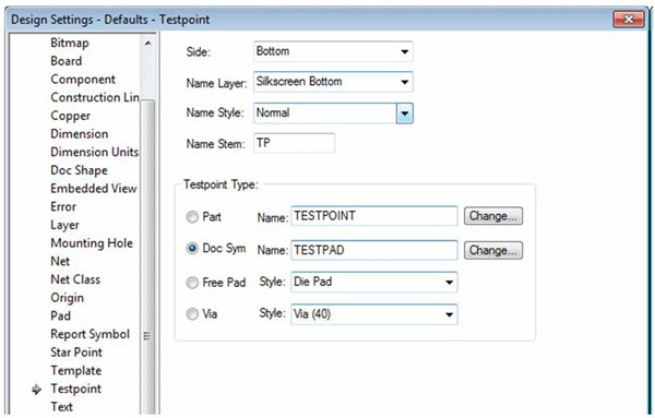
Many of the characteristics of design items are set up in the Design Settings dialog and in particular on the Defaults and Naming tabs. The Defaults page sets up the Layers, Styles, Testpoints and other feature options used when adding new items to the design.
Outputs for PCB Manufacturing
Pulsonix provides you with an output mechanism for generating professional circuit layout plots for PCB manufacturing. The plot types available will cater for home production of PCBs, right through to professional fabrication facilities. All the plot and drilling outputs are located in the CAM/Plot option on the Output menu. From this option you can select the layer, or combinations of layers to plot, the scale, the rotation, the position on the plot and the "machine" driver.
From this option you can output:
a). Gerber 274-X (extended Gerber format) and 274-D format photo-plots
b). HPGL Pen plots
c). Windows printer plots using any installed Windows driver
d). Numerically controlled drilling (NC Drill) information
e). ODB++ format
f). Format files created in the Report Maker option
g). PDF Files for documentation purposes
The aspects mentioned in this passage are some of the basic steps and functions of Pulsonix. More will be discovered when you put it into practical work.
PCBCart Is Capable of Meeting Any Kinds of PCB Manufacturing Requirements


