



Bare-die Packaging is a form of packaging that directly attaches the die to the substrate to eliminate the IC package and associated parasitics. This area is dominated by two types of interconnection: Chip-on-Board (COB) and flip chip. Both die-level assembly technologies are classified under the same banner but can be differentiated in terms of the die orientation, interconnect architecture, and consequently in terms of I/O density, process complexity and electrical performance. This difference is used in almost every engineering project downstream, including substrate design, inspection methods and more.
COB vs Flip Chip
In COB assembly, the die is put on its face with the active circuitry facing away from the substrate. Fine wire bonding – usually gold or copper – carries the electrical interconnection from the peripheral bond pads on the die to these pads on the substrate. After bonding, a glob-top epoxy encapsulant is coated on the wire loops and exposed die to protect it mechanically and to seal it to the surrounding environment.
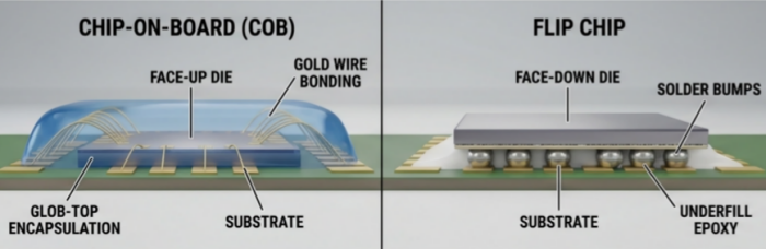
Flip chip inverts this arrangement: the die is mounted face-down, with solder bumps or copper pillars formed directly on the active surface and bonded to matching substrate pads below. This eliminates wire loops entirely, establishing a substantially shorter and more direct electrical path between die and substrate. An underfill epoxy is subsequently dispensed to reinforce the solder joints mechanically and to mitigate thermal expansion mismatch between the silicon die and substrate.
This structural distinction — peripheral wire bonding versus an area-array bump interconnection — underlies the principal differences between the two methods, including flip chip's inherent electrical performance advantage: shorter interconnects translate directly into reduced parasitic inductance and resistance, a consideration of particular significance in high-speed and RF applications.
I/O Density Considerations
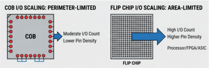
In COB assembly, I/O count is constrained by die perimeter, since wire bond pads require sufficient spacing to prevent shorting during bonding, and wire loop geometry imposes further practical limits. Pin count therefore scales with the perimeter of the die — adequate for moderate-complexity devices, but increasingly limiting as pin count requirements rise.
Flip chip circumvents this constraint through an area-array interconnect architecture. Because bumps are distributed across the entire die surface rather than confined to its edges, I/O density scales with die area rather than perimeter — and area increases disproportionately relative to perimeter as die size grows. This enables flip chip to accommodate substantially higher I/O counts and finer bump pitches, making it the preferred interconnection method for high-complexity devices such as processors, FPGAs, ASICs, and high-density memory, where wire bonding would be impractical at the required pin density.
Process and Equipment Considerations
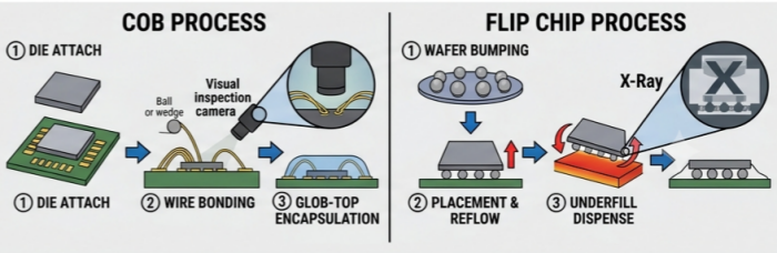
COB assembly follows a well-established sequence: die attach, wire bonding (ball or wedge), inspection, and encapsulation. Process control centers on parameters such as bond pull and shear strength, wire loop profile, and pad placement accuracy — variables that are comparatively forgiving and well characterized across the industry.
Flip chip assembly involves a more demanding process sequence. Bump formation is typically performed at the wafer level prior to die singulation, followed by high-precision placement equipment capable of fine alignment tolerances, since bump-to-pad registration accuracy is critical at reduced pitch. Bonding is achieved via reflow, thermocompression, or thermosonic methods depending on bump composition and pitch, followed by underfill dispense and cure. The combination of fine-pitch alignment requirements, additional wafer-level preparation, and joint inspection challenges — solder joints are concealed beneath the die and require X-ray or acoustic microscopy for verification, as direct visual inspection is not possible — makes flip chip a more capital-intensive and tightly controlled process relative to wire bonding.
Application Suitability
COB is generally applied to cost-sensitive designs with moderate I/O requirements, including sensor modules, smart cards, RFID components, driver ICs, and LED arrays, where board-space reduction is a priority but extreme I/O density or electrical performance is not. Its lower equipment threshold and established process maturity also make it well suited to high-mix, low-volume production environments involving frequent die-type changeovers.
Flip chip is typically reserved for high-performance, high-I/O, or space-constrained applications where wire bonding's density and electrical performance limitations become the governing constraint — processors, RF front-end modules, high-speed memory, and advanced System-in-Package (SiP) designs, where reduced interconnect length and parasitic inductance yield measurable performance benefits.
Selection between the two methods should be determined by die I/O requirements, thermal and electrical performance targets, cost constraints, inspection and rework considerations, and production volume — no single approach is universally preferable.
If your project involves COB die-level assembly, PCBCart offers a continuous production path spanning bare-die attachment and encapsulation through to PCBA, box build, and system integration — allowing device-level and system-level manufacturing to be consolidated within a single supply chain. To discuss your project's specific requirements, please contact PCBCart's engineering team.
Ressources utiles
• AOI Test
• Via-in-Pad
• SMT Packages
• Box Build Assembly Benefits
• From Prototype to Production: Managing NPI Scale-Up Risk with an HMLV EMS Partner


