



ATE (automated test equipment) load boards in the 12–20 layer range present one of the harder warpage-control problems in PCBA assembly. Thick, asymmetric copper stacks combined with laminate operating near its glass transition temperature (Tg) during reflow create a combination that standard fixturing often can't fully resolve on its own. This article covers where the warpage comes from, how fixturing constrains it during reflow, how stack-up decisions reduce it at the design stage, and where in the process to measure it.
Why High-Layer-Count ATE Boards Warp During Reflow
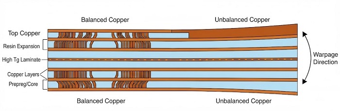
Two mechanisms dominate warpage in this board class.
Uneven copper distribution across the stack. ATE load boards typically mix dense routing layers (fine-pitch DUT interface, ground planes) with sparser signal or power layers. When copper weight and pattern density differ significantly from one layer to the next, especially across the board's neutral axis, the layers expand and contract at different rates as the board moves through the reflow profile. On a thick 12–20 layer board, that mismatch translates directly into bow and twist, since there's more laminate mass to move unevenly and more distance between outer layers for asymmetry to act over.
Laminate Tg approaching peak reflow temperature. Standard FR-4 with Tg in the 130–150°C range is already well below a typical lead-free reflow peak of 235–250°C, so the resin is fully past its glass transition for a significant portion of the profile. Above Tg, z-axis CTE increases sharply (commonly cited industry rule of thumb: several times the below-Tg rate), and the board's resistance to bending drops with it. This matters more on high-layer-count boards because:
• More layers means more accumulated CTE mismatch between copper and resin
• Longer time-above-liquidus during reflow (often required to fully wet through thick boards) extends the window where the laminate is in this compliant state
• Larger board area (common on ATE load boards to match test head footprints) increases the moment arm over which any asymmetric stress can act
Higher-Tg materials (170°C+) reduce but don't eliminate this effect. They raise the threshold; they don't remove the underlying physics.
Synthetic Stone Fixture Constraint During Reflow
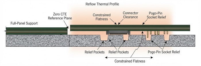
Synthetic stone (engineered granite-composite) fixtures are used because the material's own near-zero CTE and high thermal mass let it act as a stable reference plane through the reflow profile, rather than deflecting in sympathy with the board the way a metal fixture can.
The engineering logic behind this approach typically looks like:
• Full-panel support, not edge clamping. A board supported only at the edges is free to bow in the center, exactly where warpage tends to be worst. Full-panel contact from the fixture surface addresses this directly.
• Clearance for through-hole and connector features. ATE load boards commonly carry pogo-pin sockets, press-fit connectors, or through-hole components on the underside. A fixture that ignores these and forces the board flat over a protruding feature just relocates stress rather than removing it, so relief for these features is a design consideration for any full-panel fixture.
• Thermal mass matched to the profile. Because synthetic stone's CTE is negligible compared to PCB laminate, it doesn't expand or lag out of step with the board through the cycle, which helps it maintain constraint from ramp-up through peak and into cool-down, the phase where warpage otherwise tends to "set" as the resin re-passes through Tg on the way down.
The exact point at which fixture-assisted reflow becomes necessary depends on the specific stack-up, copper distribution, and panel size involved, and should be assessed case by case rather than against a fixed layer-count or thickness rule.
This is a process-level constraint applied during the thermal cycle, working alongside, not instead of, the stack-up decisions below. Fixturing manages the symptom during assembly; stack-up design manages the root cause at the design stage.
Stack-Up Design: Copper Balancing Strategy
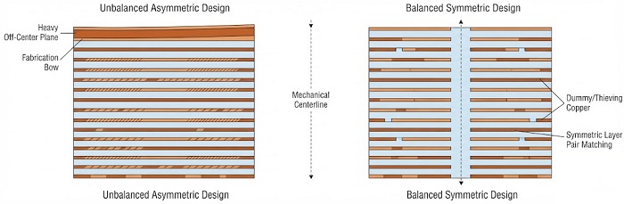
The most durable warpage fix happens before the board is built. Copper balancing means distributing copper weight and coverage symmetrically around the board's mechanical centerline: mirroring dense layers against dense and sparse against sparse, rather than letting a heavy ground/power core sit unbalanced against lighter signal layers on one side.
Common practices worth checking on ATE load board stack-ups:
• Layer-pair copper weight and density matching. Comparing copper area coverage across symmetric layer pairs (e.g., layer 2 vs. layer N-1) and keeping the delta small reduces the differential expansion that drives bow.
• Dummy/thieving copper on sparse layers. Where a routing layer is naturally light on copper (a low-density signal layer, for example), adding non-functional copper fill brings its thermal mass closer to its symmetric counterpart without affecting electrical function.
• Core vs. prepreg placement symmetry. Because cores and prepregs behave differently under thermal load, mirroring their placement around the centerline (not just mirroring copper) avoids reintroducing asymmetry at the resin-system level even when copper looks balanced.
• Avoiding a single heavy plane layer off-center. A thick, high-coverage ground or power plane placed asymmetrically in the stack is a common warpage contributor on ATE boards that need heavy current-carrying planes for DUT power delivery. Splitting that copper across a mirrored pair of layers is generally preferable to concentrating it in one.
None of this eliminates warpage risk on its own for a 16–20 layer board. It reduces the magnitude of what the reflow fixture then has to hold flat.
Measurement Checkpoints: Post-Placement vs. Post-Reflow 3D AOI
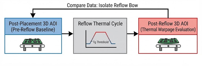
Warpage should be checked at two distinct points in the process, because the two measurements are catching different failure modes.
Post-placement 3D AOI (before reflow). At this stage, 3D AOI is primarily verifying placement accuracy and paste/component co-planarity on a board still at room temperature and thermally unstressed. Any warpage measured here is essentially "as-fabricated" bow: a baseline reflecting panel-level lamination stress, not anything reflow has introduced yet.
Post-reflow 3D AOI. This captures warpage after the board has gone through peak temperature and back to room temperature: the number that matters for downstream steps like ICT fixture contact, connector seating, or test-head mating. Comparing it against the post-placement baseline isolates how much additional warpage the reflow cycle itself introduced.
The comparison between the two checkpoints is the useful data point. A board that measures flat pre-reflow but shows significant deviation post-reflow points to the reflow profile or fixturing as the driver; a board that's already out of spec pre-reflow points back to panel fabrication or stack-up. Treating post-reflow AOI as the only checkpoint loses that diagnostic signal.
Design and Process Checklist for ATE Load Board Warpage Control
• Confirm layer count, thickness, and copper distribution against a target CTE-balanced, symmetric stack-up before layout freeze
• Specify laminate Tg with margin against the actual reflow profile peak, not just against IPC minimums
• Flag any single heavy plane layer for splitting or mirroring during stack-up review
• Plan for full-panel-support fixturing (not edge-only) on high-layer-count, high-thickness boards where inherent stiffness alone isn't reliable
• Confirm fixture relief pockets are mapped to underside connector/through-hole locations before fixture fabrication
• Capture 3D AOI warpage data at both post-placement and post-reflow checkpoints, not post-reflow alone
• Compare the two AOI checkpoints to separate fabrication-stage bow from reflow-induced bow
Getting Warpage Right on Your Next ATE Load Board
High-layer-count ATE load boards don't warp for one reason. It's usually a combination of stack-up asymmetry, laminate selection, and how the board is constrained through reflow. If you have an ATE load board project in the 12–20 layer range and want engineering input before layout freeze, submit your board specifications for a project evaluation and our team can review stack-up, fixturing requirements, and inspection checkpoints against your design.
Helpful Resources
● BGA Void Rate Acceptance Reference: IPC-7095D & IPC-A-610 Class Criteria
● IPC-A-610 Class 3 Visual Inspection Guide for Industrial & Medical Assemblies


