



Class 3 acceptance under IPC-A-610 is the tightest visual bar in the standard, and it's also the most frequently misapplied — either over-rejected out of caution, or under-enforced because operators default to Class 2 habits from prior programs. This guide covers where Class 3 actually diverges from Class 2 at the joint level, for both SMT and THT, and how visual inspection fits alongside AOI and X-ray rather than being replaced by them.
The current governing revision is IPC-A-610J, released in March 2024, which superseded Revision H (2020). J removed the "Target" condition category entirely — conditions are now classified simply as Acceptable, Process Indicator, or Defect — and substantially expanded the standard's photographic reference library to reduce inspector-to-inspector variation. All references below assume Rev J; confirm your supplier's certified revision on any quote or drawing, since acceptance language can shift between revisions.
Where Class 3 Applies — and Why It's Not Just "Stricter Class 2"
IPC-A-610 defines its three classes by the consequence of a field failure, not by product complexity:
Class 1 — General electronic products where cosmetic imperfections are acceptable and function is the only requirement.
Class 2 — Dedicated service electronics: extended service life is expected, but intermittent failure is tolerable. Most industrial automation and test equipment boards default here unless a program specifies otherwise.
Class 3 — High performance / high reliability products where continued operation is critical and field failure is not acceptable. This category commonly includes industrial control systems with safety functions, semiconductor test equipment, and non-implantable medical electronics.
Worth noting for medical-adjacent programs: we hold IATF 16949 certification but not ISO 13485, so Class 3 medical work here covers manufacturing-side visual and process rigor, not design-control or regulatory documentation support.
The real Class 2-to-Class 3 shift isn't one number — it's that Class 3 removes tolerance for ambiguity. A defect condition Class 2 accepts as a "process indicator only" (cosmetic, not reliability-relevant) often becomes a reject at Class 3, because Class 3 requires the joint's wetting to be visually confirmable rather than assumed.
SMT Solder Joint Criteria: What Tightens at Class 3
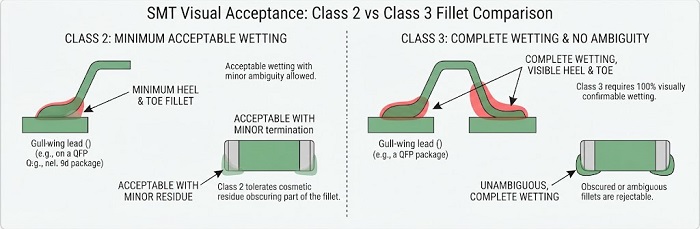
Chip components (resistors, capacitors, MLCCs). The fillet must show clear wetting up the termination on both ends. Where Class 2 sometimes tolerates a no-clean flux residue obscuring part of the fillet as a cosmetic issue, Class 3 treats an obscured or ambiguous fillet as unverifiable and rejects it. End overlap and side overhang are checked against termination and pad geometry, with materially tighter margins at Class 3 than Class 2 — consult the current Rev J tables for exact percentages, since these are dimension-specific and easy to misquote from memory.
QFP / SOP gull-wing leads. Both heel and toe fillets must be present and visibly wetted across the full lead width — not just at the toe. Lead-to-pad offset tolerance is also tighter; pad exposure beyond the accepted margin is a reject condition at Class 3 where it might carry only as a process indicator at Class 2. Common SMT solder joint defect modes like cold joints and bridging are judged against this tighter margin.
BGA and QFN. These joints sit under the package body, so "visual inspection" here can't mean naked-eye inspection alone. Where a perimeter ball is visible at the package edge, its wetting angle is checked directly. For the majority of hidden joints, wetting confirmation is functionally carried by 3D AOI (surface geometry and coplanarity) and X-ray (internal voiding and bridging) — an approach the standard's ongoing emphasis on bottom-terminated component (BTC) criteria since Rev H has reinforced. For a deeper look at how void percentage is measured and disposed against IPC-A-610 class criteria, see our BGA void rate acceptance reference. This is the core reason Class 3 BGA/QFN programs can't treat AOI and X-ray as optional add-ons — for these packages, they are the visual inspection.
THT Solder Joint Criteria: Hole Fill, Wicking, Copper Coverage
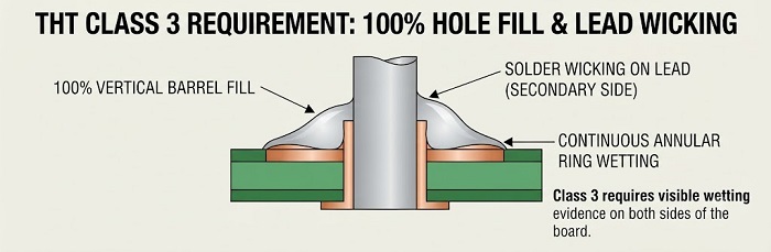
Through-hole connections remain common on industrial power and connector interfaces even on otherwise SMT-heavy boards, and Class 3 tightens three areas:
Vertical hole fill — Class 3 sets a materially higher minimum fill expectation than Class 2, with wetting evidence expected on both sides of the board wherever design permits secondary-side visibility. Exact percentage thresholds should be pulled directly from your current IPC-A-610J tables rather than assumed from memory, since this is one of the standard's more frequently cited — and frequently misquoted — numbers.
Solder wicking on the lead — Class 3 looks for wetting climbing the lead on the secondary side, not just a filled barrel. A full barrel with no wicking evidence reads as "filled" but not necessarily "wetted," and Class 3 wants the latter demonstrated.
Copper/pad coverage — continuous wetting around the annular ring is checked; partial dewetting that Class 2 accepts as cosmetic becomes a reject at Class 3 once it breaks wetting continuity beyond the accepted arc.
3D AOI, Visual Inspection, and X-Ray: A Layered System, Not a Substitute Chain
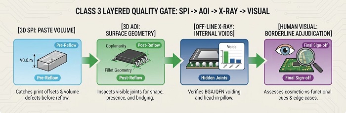
A common misconception is that automated inspection replaces human sign-off at Class 3. It's the opposite: Class 3 requires more inspection layers, because each layer covers something the others structurally can't see.
| Layer | What it catches | What it misses |
|---|---|---|
| 3D SPI (pre-reflow) | Paste volume, height, offset — before defects get baked in | Post-reflow wetting quality |
| 3D AOI (post-reflow) | Coplanarity, bridging, fillet geometry, tombstoning, component presence/polarity | Sub-package voiding, hidden bridging under BGA/QFN |
| Visual (human) | Ambiguous edge cases, cosmetic-vs-functional judgment, contamination, marking legibility | Hidden joints, high-volume statistical consistency |
| Off-line X-ray | BGA/QFN voiding, head-in-pillow, hidden bridging — including oblique-angle views for lead-frame packages | Surface wetting color/texture cues |
The practical sequencing: SPI catches paste problems before reflow; 3D AOI closes the loop on visible geometry immediately after reflow; X-ray targets the specific hidden-joint population (BGA, QFN, dense THT clusters); trained inspectors adjudicate the borderline calls that automated thresholds flag but can't classify with certainty on their own. At Class 3, dropping any one of these layers reintroduces exactly the ambiguity the class is designed to eliminate.
Rework on Class 3 Boards: Tighter Controls, Not Just "Being Careful"
Rework introduces thermal and mechanical risk that Class 3's tighter tolerances are least forgiving of. Sound practice for Class 3 rework generally includes:
A documented rework record per unit — defect location, root cause, rework method, operator, and date, tied to the board's UID via Smart MES traceability, so rework history travels with the serial number through final test and shipment.
A rework attempt limit per joint or component — repeated thermal cycling on the same pad degrades adhesion and copper integrity. Industry practice typically treats a joint that fails rework more than once as a signal to escalate to engineering disposition rather than attempt a repeated rework — the specific threshold is a program-level engineering decision, not a fixed universal rule.
Fixture-based thermal control during rework — an unsupported or warped board during hand rework can introduce new coplanarity defects. Synthetic stone fixtures hold the board flat and help manage localized heat during hot-air or iron rework.
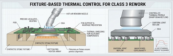
Mandatory re-inspection after rework — the reworked joint, along with adjacent joints disturbed by the process, should return through 3D AOI before the unit continues downstream. A reworked Class 3 joint without a documented re-AOI pass is, by definition, an unverified joint.
Where Judgment Calls Actually Happen
Most Class 3 rejects and false-rejects cluster around a recurring set of visual scenarios: marginal wetting angle on a gull-wing heel, ambiguous voiding percentage on a BGA X-ray image, borderline hole fill on a THT connector, cosmetic-versus-functional dewetting on a chip component. These are exactly the calls where inspector training and reference imagery — the area IPC-A-610J expanded most — matter more than a written spec number alone.
Have a specific Class 3 acceptance question, or an X-ray/AOI image you're trying to disposition? Reach out and our team can walk through it against the current IPC-A-610 criteria for your application.
Ressources utiles
• Quality Control Methods for BGA Solder Joints
• BGA Soldering Technologies in SMT Assembly
• Engineer-Friendly Methods for Optimal Solder Joints in BGA Assembly
• First Article Inspection
• BGA Packaging vs. Traditional SMT/SMD Rework Comparison


