



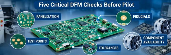
At Rev A, a DFM review asks whether the board can be built and powered up at all. At pilot, it asks whether the same board can be built again and again, in a panel, on a line, from parts you can still buy next month, and tested without an engineer holding a probe. Most things you tolerated on the prototype turn into fix-before-pilot items: panelization, fiducials, test access, component availability and tolerances.

What can you live with on a prototype?
Quite a lot, and that is fine. A Rev A build exists to answer design questions: does the power tree come up, does the firmware talk to the sensor, does the layout hold together. Nobody should delay a first spin to perfect assembly yield.
The things we routinely see pass on a prototype are these. A board shipped as a single piece or loosely routed array, because someone will hand-place or hand-feed it anyway. Fiducials that are missing or sitting too close to the board edge. No dedicated test points, because the engineer will clip onto a via or a resistor leg. A BOM with a part that has a single source and a long wait, because the quantity is small enough to buy from a distributor's stock. A connector footprint that needed a file or a bit of persuasion. Silkscreen over pads. A tolerance stack nobody has analysed, because the one board that fits is the only board that exists.
Each of those is cheap to absorb at quantity one to five and expensive at quantity fifty with a fixture and a program already built. The point of the Rev A review is to separate "this will annoy us now" from "this will fail the line later", and to write the second group down while it is still fresh. If you are choosing between prototype and standard builds, our piece on PCB prototyping vs standard PCB covers where the two paths split.
One more thing belongs here. A prototype run often hides problems because it gets human attention at every step. An engineer nudges a part, reflows a joint, swaps a connector that would not seat. None of that is visible in the build record, and none of it survives into pilot.
What has to be fixed before pilot?
Pilot is the first run where the line sets up for you as a repeatable process. Stencils are made, a placement program is built, inspection programs are tuned, and a fixture may be machined. Every compromise you carried from Rev A now costs setup time or yield, so this is where we push for changes. Five areas come up almost every time.
Panelization
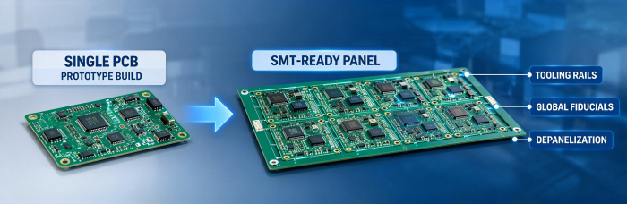
A prototype can travel as a single board. A pilot run usually cannot. The board has to be handled by conveyors, supported through printing and reflow, and separated after assembly without stressing parts near the edge. That means a defined array, rails or tooling holes where the line needs them, and a depaneling method chosen with the component layout in mind. Tall parts, edge connectors and ceramic capacitors close to a break line are the usual troublemakers.
The specific rail widths, array limits and tooling hole requirements are on our panel requirements page, and anything outside those should be confirmed with our engineering team before you freeze the panel drawing. We would rather see a panel question at pilot kickoff than after the stencils are cut.
Fiducials
Placement machines and 3D AOI both need something to register against. Global fiducials on the panel and local fiducials near fine-pitch parts let the line correct for board shift and stretch. On a prototype, a missing fiducial just means a slower, more manual setup. In pilot, it means the machine has to guess, or the operator has to correct by eye, and neither is a process you want to hand to a second shift. Check that fiducials are on every layer that carries parts, that the surrounding area is clear of mask and silkscreen artifacts, and that the pattern is identical across panel and board. For exact size and clearance values, confirm with our engineering team.
Test points
Rev A can be debugged with a scope and patience. Pilot needs a test strategy, and the layout has to support it. Decide now whether the board will see in-circuit test, flying probe, or a functional fixture, because each one wants something different from the layout: access on one side, spacing between points, keep-outs around tall parts, a consistent location for programming and power pins. A synthetic stone fixture is a reasonable way to hold a board for functional test, but it only works if the points are where the fixture expects them. If you add test points after the layout is released for pilot, you are respinning the board, which is the expensive version of this change.
Adding test points at Rev B costs a few hours of layout. Adding them after a fixture is built costs a fixture.
Component availability
This is the one that most often surprises hardware teams. A part that was easy to find for a handful of boards may be on allocation, end-of-life or single-sourced when the pilot BOM goes out. Before pilot, we want to see manufacturer part numbers on every line, approved alternates where the design can tolerate them, and a flag on any part with a long wait or a minimum order well above the pilot quantity. Moisture-sensitive parts, fine-pitch BGAs and anything that needs special handling should be called out so they can be planned for, not discovered at the feeder.
We do not give delivery commitments from a BOM scan alone. What we can do is tell you which lines look risky and let you decide whether to redesign, approve an alternate or buy ahead.
Tolerances
On a prototype, if a connector sits a little proud or a heatsink needs a nudge, you fix it with the tool in your hand. In pilot, each part sits where the placement machine puts it, within the tolerance of the pad, the part and the process. That includes component-to-component clearances, connector alignment to the enclosure, keep-outs around mounting holes and pad design for parts that tend to float or tombstone. Where a mechanical fit matters, we ask for the 3D model and the tolerance assumptions behind it, because a stack-up that works on one hand-built board tells you very little about fifty.
Pad geometry on fine-pitch and bottom-terminated parts deserves the same scrutiny. Voiding under thermal pads and BGAs is something we check with offline X-ray when the design calls for it, and it is much cheaper to tune a paste aperture at pilot than to chase intermittent failures later. General layout habits help here, but part-specific pad and stencil decisions are best reviewed with the actual footprint and paste layer.
Who should own each fix?
Not everything is the layout engineer's problem, and a lot of delay at pilot comes from nobody being sure who is holding which item. We do not provide schematic design, so design-side changes sit with your team. A rough split that works in practice:
Your design team owns anything that changes the Gerber or the schematic: test point additions, fiducial placement, pad geometry corrections, connector or footprint changes, silkscreen cleanup.
Your procurement or supply chain lead owns the BOM: approved alternates, manufacturer part numbers, buy-ahead decisions on risky parts, and the call on whether to redesign around a hard-to-source component.
Your mechanical engineer owns the tolerance questions that involve the enclosure, heatsinks and connectors, and the 3D model that goes with them.
Our engineering team owns the manufacturing review: flagging panel concerns, checking footprints against our process, reviewing stencil and paste decisions, setting up the placement and inspection programs, and telling you where a design choice will cost yield. Setup, SPI and AOI programming, X-ray inspection and MES traceability on our side all depend on getting clean inputs from yours.
Your quality or test lead owns the test strategy: which fixture, which coverage, and what pass criteria go on the traveller.
The single most useful habit is naming one person on your side as the decision owner for the pilot DFM report. When three engineers each answer a different question from the same report, we end up with three versions of the BOM.
If you want a quick sanity check before the formal review, you can send us the Gerber and BOM for a free DFM check and see what comes back. It will not replace a full pilot review, but it catches the obvious items early.
Rev A vs pilot DFM comparison
| Review area | Rev A (prototype) | Pilot run |
|---|---|---|
| Main question | Does the design work? | Can the process repeat it? |
| Board format | Single board or loose array is acceptable | Defined panel with rails and tooling features suited to the line |
| Fiducials | Nice to have, often skipped | Required on panel and near fine-pitch parts; checked before program setup |
| Test access | Probe onto vias or leads | Test points laid out for the chosen test method and fixture |
| BOM | Distributor stock, loose alternates | Manufacturer part numbers, approved alternates, sourcing risks flagged |
| Footprints | Hand-fixable | Verified against part datasheet and process; paste layer reviewed |
| Tolerances | Fit by hand adjustment | Stack-up reviewed with mechanical model; placement tolerance accepted |
| Inspection | Visual, spot checks | 3D SPI/AOI programs; X-ray for hidden joints where the design needs it |
| Traceability | Informal notes | Lot and serial data recorded in Smart MES |
| Typical outcome | List of items to carry forward | Design release with confirmed changes before setup |
What should you bring to the pilot DFM review?
A short list helps more than a long one. We usually ask for:
Gerber files and drill data, with a fabrication drawing and stack-up.
A BOM with manufacturer part numbers, quantities and any approved alternates.
Pick-and-place data and an assembly drawing, including polarity marks and any special instructions.
The test plan: which method, which fixture, which programming steps.
The Rev A issue log, including anything your team fixed by hand.
Any mechanical constraints that affect part placement or board outline.
The Rev A issue log is the one people forget, and it is often the most valuable. Items that took a rework iron on the prototype are the exact ones that will bite at pilot.
FAQ
Do we need to freeze the design before the pilot DFM review?
Not fully, but you should freeze what the process depends on: board outline, panel intent, footprints, and test strategy. A review run on a layout that is still moving gives you a list that goes stale within a week. If some items are open, mark them in the package so we know which findings are provisional.
Should we run a second prototype spin before pilot?
Sometimes. If Rev A exposed functional problems, a Rev B is the right call, and it is also the cheapest time to add fiducials, test points and panel features. If Rev A worked and the open items are all manufacturing-side, going straight to pilot with a reviewed design is usually reasonable. The decision depends on how many fixes touch the copper.
What if a part on the BOM has no alternate?
Then tell us early. We can flag the risk, but substituting a part without your sign-off is not something we will do. Your options are to redesign around it, buy ahead, or accept the risk and plan around it. Which one makes sense depends on your build quantity and schedule, and that conversation is easier before the pilot order than after.
How do we handle a mechanical fit issue found at pilot?
Send us photos and measurements of the affected area, along with the 3D model if you have one. Often the cause is a footprint or placement offset we can see in the data. If the fix requires a layout change, it goes back to your design team, and we update the program once the new files are released.
Can the same DFM report be reused for the next production order?
Partly. Panel, fiducial and footprint findings usually carry forward as long as the design has not changed. BOM and sourcing findings age quickly, so expect to revisit them before each order. Any engineering change should trigger a fresh review of the affected areas.
Helpful Resources
• Why Your HMLV Prototypes Need a 200-Point DFM Check Before Production?
• Influence on Printing Quality of PCB Based on Bad Design of Fiducial Marks
• Test Point Design Guidelines for ICT & Flying Probe Testing on Life Sciences PCBA
• Mastering Complexity: How We Manage 1000+ Active BOMs in HMLV PCB Assembly
• PCB Pre-order Checklist


