



Chip-on-board assembly hinges on two process steps that determine whether a die will survive its working life: how it's attached to the substrate, and how its bond pads are electrically connected to the board. Get either wrong and the failure often doesn't show up until the device is in the field. This article goes a level deeper into how die bonding and wire bonding actually work, and what can go wrong along the way. (For a quick refresher on COB terminology, see PCBCart's glossary entry on chip-on-board and glob top.)
Die Attach Methods: Conductive vs Non-Conductive Adhesive
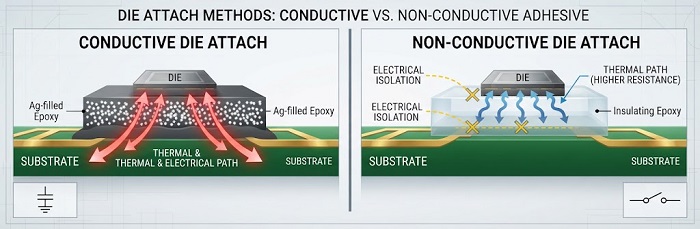
Before any wire bonding happens, the bare die has to be mechanically fixed to the substrate. The adhesive chosen for this step isn't just about mechanical hold — it also affects the die's thermal path and, in some designs, its electrical connection to the board.
Conductive die attach typically uses a silver-filled epoxy or similar material. This creates an electrical path between the underside of the die and the substrate, which matters when the die's back side needs to be grounded or when the design uses the substrate as a heat spreader. The conductive filler also improves thermal conductivity, helping pull heat away from the die during operation.
Non-conductive die attach is used when the underside of the die must stay electrically isolated from the substrate — for example, when all electrical connections are made exclusively through the bond wires on the top side. Non-conductive adhesives are generally chosen for their cure behavior, stress absorption, and compatibility with the substrate material, since electrical performance isn't the deciding factor.
In both cases, the adhesive layer also has to absorb some mechanical stress from the mismatch in thermal expansion between the die and the substrate. A poorly chosen or poorly applied adhesive can lead to voiding or delamination that surfaces later as a reliability problem rather than an immediate defect.
Wire Bonding Basics: Materials and Why Fine Wire Is Used
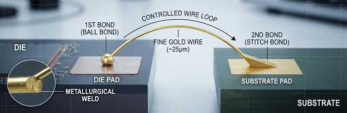
Once the die is attached, wire bonding creates the electrical connections between the die's bond pads and the substrate traces. Gold wire bonding is the most common approach for COB work, chosen for its combination of electrical conductivity, corrosion resistance, and ease of forming a reliable bond at the pad. Other materials, such as aluminum or copper wire, are used in specific applications, but gold remains the standard reference point for general-purpose COB assembly.
The wire itself is extremely fine — typically in the range of tens of microns in diameter. This isn't an arbitrary choice. Fine wire allows the bond to form without applying excessive force or heat to the die, which is critical given how small and closely spaced modern bond pads are. Finer wire also bends and loops more predictably, which matters for keeping wire shape consistent across hundreds of bonds on a single die or panel.
Each wire bond is formed in two stages: a first bond at the die pad, and a second bond at the corresponding substrate pad, with a controlled wire loop connecting the two. The shape and height of that loop matters — too flat and the wire risks contact with the die edge or neighboring wires; too high and it becomes vulnerable to damage during handling or encapsulation.
Why Post-Bond Inspection Matters
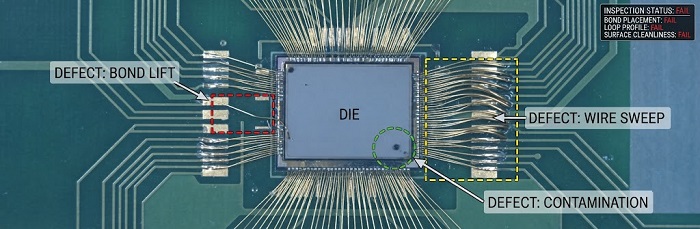
Wire bonds are inspected before encapsulation for a simple reason: once glob top or another encapsulant covers the die and wires, defects become effectively unfixable and often invisible until the unit fails in test or in the field.
Inspection at this stage typically checks bond placement accuracy, loop height and shape, and pull strength (a destructive or sample-based test that confirms the bond can withstand mechanical stress). Because encapsulation locks in whatever state the assembly is in, this is the last practical point to catch a weak or misplaced bond before it becomes a hidden defect.
Common Failure Modes to Be Aware Of
A few failure modes come up repeatedly in wire-bonded COB assemblies:
Bond lift — the wire separates from the pad, usually due to insufficient bond formation or contamination on the pad surface at the time of bonding.
Wire sweep — during encapsulation, the flow of the glob top material can physically push or deform the fine wire loops, sometimes causing shorts between adjacent wires.
Contamination — particles or residues on the die surface or bond pads before bonding can prevent a proper metallurgical bond from forming, leading to intermittent or immediate failures.
Understanding these failure modes is part of why die attach, wire bonding, and inspection are treated as a connected sequence rather than isolated steps — a weakness introduced early often only becomes visible several steps later.
If you have a COB or die-level assembly project in development, visit PCBCart's [PCB Assembly service page] to learn more about how we support high-mix, low-volume production needs.
Helpful Resources
• AOI Test in PCB Assembly
• Advanced PCB Assembly Capabilities
• PCB Assembly Overview


