



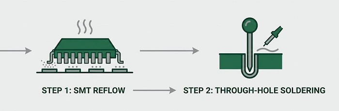
On a mixed-technology board, surface-mount parts are normally placed and soldered first, and through-hole parts are added afterward. That order is a process constraint your design inherits, not a preference you can trade away. It means every part is also a heat-exposure decision: what it must survive, which side it sits on, and how much room the later through-hole step needs around it.
Why Mixed Boards Are Soldered in That Order
The logic starts with how surface-mount soldering works. Solder paste is printed through a stencil onto flat pads, components are placed into that paste, and the whole board goes through reflow. Through-hole bodies and leads standing on the board would get in the way of printing and placement, so they have to wait. The second reason is heat. A joint that has already been soldered will melt again if it passes through another soldering step, which is why reversing the order risks disturbing joints that were already finished, with parts shifting or even dropping off the board.
None of this is exotic. It is simply the reason the order exists. What matters for a buyer is what follows from it, because the sequence quietly decides which components a given design can use and where they can go.
What the Sequence Does to Your Component Choices
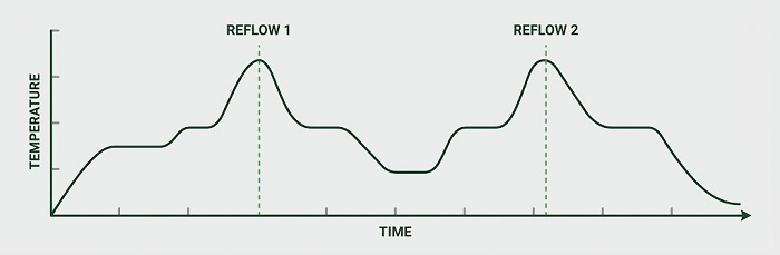
The first consequence is a heat budget. Every surface-mount part on the first reflowed side goes through reflow, and on a double-sided board the parts on the second side may go through it again. Each component's datasheet states a maximum soldering temperature and exposure time, and moisture-sensitive parts carry an additional handling limit. A part that looks perfectly ordinary on a schematic can still be a poor fit if its rating leaves no margin for the number of thermal cycles the board will see.
The second consequence runs the other way. Parts that cannot tolerate reflow heat are usually the ones left for the through-hole step. Plastic-bodied connectors, electrolytic capacitors and relays are common examples, though the datasheet, not the part category, is what settles it. In that sense the sequence is not only a limit. It also tells you where a heat-sensitive part can safely live: on the through-hole list, added after the board has already been reflowed.
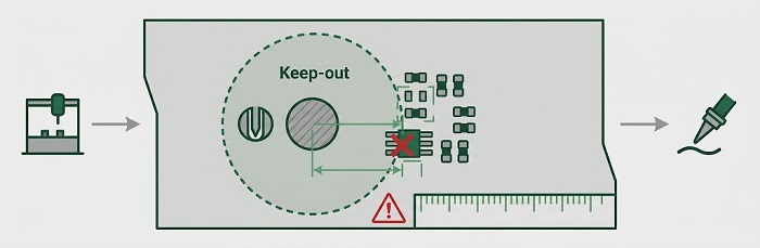
The third consequence is layout. The through-hole step works from the side where the leads protrude, and the equipment that solders them needs physical access around each pin. Depending on the soldering method and the fixture used, surface-mount parts on that same side, close to through-hole pins, can be a problem. They may need keep-out space or protection, and the distances involved vary from supplier to supplier, so they are worth asking for rather than assuming. Some assemblers also use pin-in-paste, in which paste is placed in the holes and the through-hole leads are soldered during reflow, but that technique only works for parts rated for reflow heat and only if the supplier actually offers it.
There is also a trade-off hiding in the choice between a through-hole part and its surface-mount equivalent. Converting a part to surface mount can remove a whole process step from the board, but connectors that take mating force or cable strain are often through-hole for mechanical retention, and swapping them is a mechanical decision before it is an assembly one.
It is also worth looking at how many through-hole parts the design actually needs. A board with only one or two of them still has to go through a separate soldering step for those few parts, so the process cost of a mixed board is often out of proportion to the parts that cause it. Before committing to that step, it is reasonable to ask whether each through-hole part is there for a mechanical reason, or simply because it was on the previous revision. Consolidating or replacing the ones that have no mechanical justification can simplify the build without touching the rest of the design.
What to Settle Before You Send Files
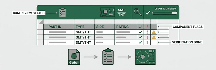
Most of these conflicts are cheap to resolve on paper and expensive to discover on a built board, which is why the first useful step is to make the information visible. Mark every part's mounting type and side in the BOM, flag anything with a restricted soldering rating, and say so plainly if a through-hole part must not go through reflow. Then ask the supplier which method they will use for the through-hole step and what keep-out space it needs. A design review is the natural place for these questions to surface, and PCBCart lists a free Valor DFM/DFA check among its assembly services for exactly this kind of problem.
A few patterns come up repeatedly. Assuming through-hole can go anywhere on the board is the most common one, because the pin side needs access that surface-mount parts can block. Treating a part's soldering rating as a formality is the second, since a rating with no margin for multiple heat cycles becomes a quality problem on a double-sided build. Swapping a through-hole part for a surface-mount one late in the design is the third, because it changes the mechanical behavior of the part, not just the process it goes through.
FAQs
1. Can through-hole parts go through reflow instead?
Sometimes, using pin-in-paste, but the parts must be rated for reflow heat and the supplier must offer the process. Ask before designing around it.
2. Why can't through-hole parts be placed first?
Their bodies and leads obstruct paste printing and placement, and joints they form would face a second heat step.
3. Does a mixed board cost more than a surface-mount-only board?
It adds a process step, so ask for it to be quoted explicitly rather than assuming the price is the same.
4. Should I replace a through-hole connector with a surface-mount version?
Only if the mechanical load allows it. Connectors that see mating force are often through-hole for strength.
5. Who decides how the through-hole step is soldered?
The supplier, based on the board and parts. Ask which method applies and what keep-out space it needs.
If your design mixes both technologies, a BOM that already marks each part's type and side makes the first conversation with any supplier much more productive.
Get an Instant Quote for PCB Assembly
Helpful Resources
• Comparison between Through-Hole Assembly (THA) and Surface Mount Assembly (SMA)


