



A reflow profile is the temperature-over-time path a board follows through the oven. It has to be set for the board in front of the operator, not once for every board, because thermal mass, component mix, and board construction change how heat reaches each joint. We assemble with lead-free solder, which leaves a narrow margin for error, so the information you give us about heat-sensitive parts and unusual boards matters more than most buyers expect.
What a Reflow Profile Actually Does
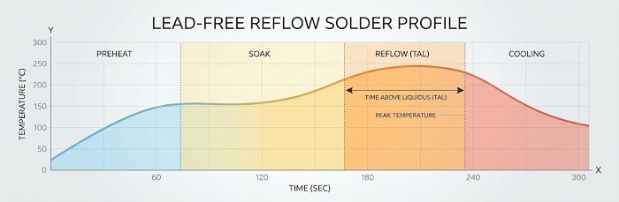
Reflow soldering melts solder paste that has already been printed onto the pads, so that it flows around the component terminations and then solidifies into a joint. The oven does this in stages. The board is warmed gradually, held at a steady temperature so that different parts of the board can catch up with each other, taken above the melting point of the solder for a controlled time, and then cooled.
Each stage protects something. Gradual warming protects components from thermal shock. The hold lets the heavy areas of the board approach the temperature of the light ones. The time above melting point forms the joint, and the cooling stage affects how the joint finishes. A profile that gets one stage wrong can produce defects that do not show up until later inspection.
Why One Profile Cannot Serve Every Board
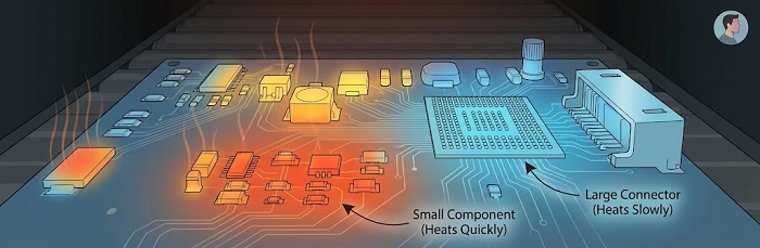
The temperature you set on the oven is not the temperature the board reaches. A large ground plane, a heavy connector, or a big BGA absorbs heat slowly, while a tiny resistor next to it heats almost immediately. The goal of profiling is to bring every joint to the right condition while keeping every component inside its own limit, and the gap between the hottest and coldest points on the board is what makes that difficult.
Board construction adds to the problem. We assemble rigid, flexible, and metal-core boards, and each behaves differently in an oven. A thick, copper-heavy board lags behind the oven setting. A thin flexible board responds quickly and needs to be supported. A metal-core board conducts heat away from the components in a way that an FR-4 board does not. The same oven and the same paste will therefore need different handling from one board to the next.
Lead-free solder makes this less forgiving. It melts at a higher temperature than traditional tin-lead solder, so there is less room between the temperature at which the joints form and the temperature that the most sensitive part on the board can tolerate. Because our assembly uses lead-free, RoHS-compliant solder, that narrower window applies to every board we build.
How Profile Problems Show Up on the Board
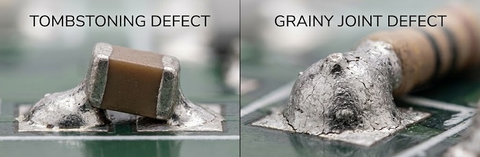
When a profile is wrong, the symptoms are familiar. A small chip component that stands up on one end, known as tombstoning, often points to the two pads heating unevenly. Dull, grainy, or incomplete joints suggest the solder did not get enough heat for long enough. Cracked parts or discolored areas suggest the opposite. Voids inside a joint, and warping of a thin or large board, can also have heat as a contributing cause.
These symptoms matter to a buyer because they rarely have a single cause. Paste volume, component placement, and the design itself also play a part, so a defect should not be blamed on the oven alone. But the pattern is informative. If the same defect appears on the same part, board after board, the question to ask is what is different about that part's thermal surroundings.
Consider two boards built in the same week. The first is a small, light board with mostly small passives. The second is a thick board with a large heat-absorbing connector in one corner. The first is forgiving, and almost any sensible profile will work. The second needs more thought, because the connector will lag far behind the rest of the board. Both boards are legitimate designs, and both can be built well. The difference is that the second one benefits from a conversation before the first build.
What You Can Do to Make Profiling Easier
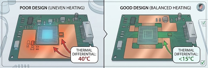
Most of the useful decisions are made in the design. Balanced copper distribution helps, because large copper areas on one side of a component and none on the other create uneven heating. Keeping heat-sensitive parts away from heavy thermal mass reduces the spread of temperatures across the board. Thermal relief on pads connected to large planes also helps the joint reach temperature at the same time as its neighbors.
The second contribution is information. Flag parts with limited temperature ratings in your BOM, and mention any moisture-sensitive parts. Tell us if the board is unusually thick, copper-heavy, or flexible. Double-sided boards deserve a note too, since the second side goes through its own heat cycle after the first. A free Valor DFM/DFA check is part of our assembly service and is a good moment to raise any of these points.
A few mistakes come up repeatedly. Assuming the datasheet's maximum temperature is a target forgets that the board and the oven are not at the same temperature. Leaving temperature-limited parts unmarked means nobody knows which component sets the limit. Placing a sensitive part beside a heavy connector creates exactly the temperature difference that profiling struggles with. Treating a flexible or metal-core board like an ordinary rigid one overlooks how differently it heats.
FAQs
1. Do you assemble with lead-free solder? Yes. Our assembly uses lead-free, RoHS-compliant solder.
2. What should I tell you about my board? Mention heat-sensitive or moisture-sensitive parts, and say if the board is thick, copper-heavy, flexible, or metal-core.
3. Does a double-sided board go through reflow twice? Often, yes. Each side is reflowed in turn, so parts on the first side see heat a second time.
4. Why not set the oven to the part's maximum rating? Board temperature differs from the oven setting and varies across the board, so a safe margin is needed.
5. Are heavy boards harder to reflow? They can be, because large copper areas absorb heat slowly. Raise this during design review.
A profile is only as good as the information behind it, so the most useful thing a buyer can send is a BOM that shows which parts set the limits.
Get an Instant Quote for PCB Assembly
Helpful Resources
• Essential Elements in Reflow Soldering Technology for BGA Components
• Common SMT Defects and How to Avoid Them
• Mitigating Moisture Sensitivity Level (MSL) Risks in High-Density SMT Assembly


