



For a press-fit connector, the dimension that matters is the finished plated-through-hole diameter, together with the barrel copper, hole-wall finish and board thickness the connector manufacturer specifies. The drill diameter is not the controlling dimension. Put those requirements on your fabrication drawing and in your order, identify the exact connector document they come from, and ask your fabricator to confirm how it will meet and verify them before tooling.
Drill size is a process input that the fabricator selects to reach the finished condition. Copper plating, surface finish and board construction all sit between the two numbers. When a drawing shows only a nominal “hole size”, the fabricator and the assembly team can end up working from different assumptions, and the first sign is usually a connector that will not seat, or one that seats too easily.
Key Takeaways
• Specify the finished plated-hole diameter and its tolerance from the connector manufacturer’s application specification. The drill size follows from it.
• The same connector can require different drilled and finished sizes for different PCB finishes, so a finish change is a design change.
• A correct diameter is not enough. Barrel copper, hole-wall finish, board thickness, flatness and hole position all affect the press-fit joint.
• Press-fit windows are often tighter than standard PTH tolerances. Flag them as special requirements instead of relying on default tolerances.
• Agree how the holes will be measured, and what evidence you need, before production starts.
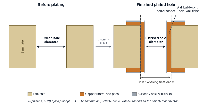
Figure 1. Drilled opening versus finished plated hole. Schematic only; not to scale.
Which Hole Size Does the Connector Drawing Specify?
Start with the application specification and customer drawing for the exact connector part number and revision. Check whether each dimension refers to the drilled hole, the finished plated hole or a different feature, such as a locating hole. These dimensions are not interchangeable.
| Term | What it describes | Why it matters |
|---|---|---|
| Drill diameter | The nominal diameter of the tool selected for drilling | A fabrication process input, not the final mating dimension |
| As-drilled hole diameter | The actual opening produced before plating | Can differ from the nominal tool diameter |
| Finished hole diameter | The opening left after the specified hole-wall copper and finish | The dimension the press-fit contact engages |
| Pad diameter | The copper land surrounding the hole | Defines surrounding copper geometry, not the contact opening |
| Hole position | The location of the hole relative to the specified datums | A correct diameter does not guarantee that a connector array will align |
A Real Example: One Connector, Three PCB Finishes
TE Connectivity’s application specification 114-13021 (Rev C) for PC/104 and PC/104-Plus connectors shows how these requirements are written in practice. For the press-fit (eye-of-needle) contacts of the PC/104 version, on a 1.57 mm FR-4 board with 0.025–0.075 mm of barrel copper, it specifies:
| PCB finish | Drilled hole diameter | Finished hole diameter after plating |
|---|---|---|
| Tin-lead | 1.13–1.17 mm | 0.95–1.11 mm |
| Immersion silver | 1.18–1.22 mm | 1.10–1.19 mm |
| ENIG | 1.18–1.22 mm | 1.10–1.19 mm |
Source: TE Connectivity application specification 114-13021, Rev C, Figure 4 (PC/104 version only; PC/104-Plus values differ).
Two points stand out. First, the specification controls both the drilled and the finished diameters, not just one of them. Second, moving from a tin-lead finish to immersion silver or ENIG shifts both windows. A finish change that looks cosmetic on an order form changes the press-fit interface. The same document also states that the customer drawing for a specific part takes priority over the application specification if the two conflict, so always work from the documents for your exact part number.
These values show how a connector manufacturer defines the hole. They are not a recommendation for any other connector. Do not copy a hole size from a visually similar part; obtain the requirements for the connector you have actually selected.
Also distinguish electrical press-fit contacts from mechanical features. A boardlock or locating peg that holds the connector in position may have different hole requirements from the signal and power contacts.
Why Is the Drill Size Larger Than the Finished Hole?
Hole-wall plating occupies space inside the drilled opening. As copper and finish are deposited on opposite walls, the available diameter shrinks. A simplified geometric relationship is:
Finished diameter ≈ diameter before plating − 2 × t
Here, t is the radial thickness of everything deposited on the hole wall that is included in the finished dimension: barrel copper plus any hole-wall finish. As a purely illustrative case, a round opening that measures 1.00 mm before plating and receives a uniform 0.025 mm deposit on each wall would finish at roughly 0.95 mm. These are demonstration numbers only, not a recommended press-fit construction or a PCBCart process value.
The relationship explains why the two diameters differ, but it is not a drill-selection rule. The fabricator also has to account for the actual drilled opening, plating distribution along the barrel, process variation and the specified finish. A nominal tool size is not a guaranteed measurement of the hole before plating.
Some connector specifications go further and restrict how the finished size may be reached, for example by prohibiting an oversized drill that is then plated down to size. That is why the drill requirement belongs in the tolerance agreement below. The practical instruction, therefore, is not “add a standard allowance to every hole.” It is “identify the required finished condition, then agree on the manufacturing approach.”
Is the Correct Finished Diameter Enough?
No. Two holes can have the same final opening but different copper thicknesses, finishes or board constructions, and those differences matter because a press-fit joint is both an electrical and a mechanical connection.
A compliant press-fit pin has a press-in zone that is slightly larger than the plated hole. During insertion, that zone deforms and keeps a normal force against the barrel, which is what creates a gas-tight, low-resistance contact. TE describes the pin and the plated through hole as one press-fit system whose behavior depends on the properties of both. Too little force weakens the joint; too much can damage the barrel or the surrounding laminate. Before releasing the board, review the following requirements together.
Hole-Wall Copper and Finish
Check the connector manufacturer’s requirements for barrel copper thickness and for the finish inside the hole. A surface-finish selection on the PCB order should not replace a review of the connector’s permitted hole-wall construction. Where the specification distinguishes copper, underplating and final finish, keep those distinctions in your requirements, and do not assume a finish change is harmless just because the finished diameter is unchanged.
Board Thickness and Flatness
Confirm the board-thickness range the connector manufacturer permits and how that thickness is defined. A change in PCB thickness should trigger a connector-interface review rather than being treated only as a mechanical enclosure change. Flatness can be specified too: the PC/104 application specification cited above, for example, limits board bow to 0.08 mm over the length of the connector.
Hole Location and Pattern
For a multi-pin connector, review the hole array against the connector drawing. Diameter tolerance and positional tolerance answer different questions, and tightening one does not resolve the other. State the required datums and positional controls on the drawing rather than relying on an unspecified general tolerance.
Processing Before Insertion
Identify whether the board will pass through reflow, wave soldering or other processing before the connector is inserted. Where the connector’s application specification sets restrictions on prior processing, communicate them to both the fabricator and whoever performs the insertion.
Which Tolerances Should Be Agreed Before Fabrication?
Use the connector’s requirements as the starting point, then obtain fabrication confirmation. Do not assume a standard PTH tolerance satisfies a press-fit interface. For reference, these are the standard tolerances we publish for the features most relevant to press-fit holes:
| Feature | PCBCart standard tolerance |
|---|---|
| PTH finished diameter, ≤0.8 mm | ±0.08 mm |
| PTH finished diameter, >0.8 mm to <2.5 mm | ±0.10 mm |
| Hole location (drilling) | ±0.18 mm |
| Finished board thickness, >1.0 mm to ≤1.6 mm | ±0.14 mm |
| Finished board thickness, >1.6 mm to ≤2.0 mm | ±0.18 mm |
Compare that with the ENIG example above. Its finished-hole window spans 0.09 mm (1.10–1.19 mm), which is less than half of the ±0.10 mm band our standard tolerance allows for a hole of that size. A requirement like that has to be stated as a special requirement; it will not be met by default. Our standard tolerances are a general baseline, not an approval of a particular press-fit construction, and tighter values can be considered for custom projects once we have reviewed the full requirement.
| Requirement | What to establish | What to avoid |
|---|---|---|
| Finished hole diameter | Nominal, permitted range and the stage at which it is measured | An unexplained “hole size” |
| Drill requirement | Whether the connector specifies a drilled-hole range or leaves drilling to the fabricator | Treating all drill values as freely adjustable |
| Hole-wall copper | Required thickness or range from the applicable specification | A generic plating note with no interface review |
| Hole-wall finish | Permitted finish system and applicable limits | Assuming all solderable finishes are interchangeable |
| Board thickness and flatness | Allowed range, measurement basis and any bow limit | A nominal thickness without a compatibility check |
| Hole pattern | Datums, pitch and positional requirements | Assuming a correct diameter guarantees alignment |
| Document revision | Connector drawing and application-specification revisions | Referencing only a connector family name |
If the connector specification controls both drilled and finished dimensions, send both. The fabricator should review them together rather than silently overriding one to achieve the other.
What Should Appear on the Fabrication Drawing?
Identify the affected holes and state the required finished condition in a local detail or controlled note, not in a general PTH statement. Keep the drawing, drill data and order requirements consistent with each other. Supply Excellon drill data with a drill tool list that shows finished sizes and plating status for each tool, as explained in our guide to choosing a fabrication data package. The following is a drafting template, not a completed production specification:
|
PRESS-FIT CONTACT HOLES — CONNECTOR J[X]
Connector manufacturer: Exact connector part number: Connector drawing number and revision: Application specification number and revision:
Affected holes / drawing detail: Finished plated-hole diameter and tolerance: Drilled-hole requirement (if specified): Measurement stage: Hole-wall copper requirement: Permitted hole-wall finish: Finished PCB thickness and tolerance; bow limit: Hole-pattern datums and positional requirements:
Manufacturing and inspection requirements to be reviewed and agreed before fabrication. Do not change the specified hole construction without written engineering approval. |
Replace every blank with a verified requirement or an explicitly agreed disposition. “Per connector datasheet” is not enough if the package does not identify the document and its revision.
On PCBCart orders, the specifications entered on the online order form define the board build, and separate readme or specification files are not used to set parameters. Put your press-fit requirements in the Special Requirement Note when you order as well as on the controlled drawing, and make sure the two say the same thing.
What If the Drill File and Drawing Disagree?
Stop and resolve the discrepancy before fabrication. First, establish what the drill-file diameters represent in your data handoff. Then compare them with the finished-hole callouts and any connector-imposed drilling requirements.
Not every difference is an error: a drill diameter and a finished diameter are expected to differ. The problem is an unexplained difference between documents that are supposed to describe the same requirement. A useful clarification request identifies:
1. The affected connector and hole group.
2. The diameter shown in each file.
3. Whether each value is intended as drilled or finished.
4. The controlling connector document and revision.
5. The corrected files or the written disposition.
After clarification, issue a consistent manufacturing package. Avoid leaving a correction only in an email while the released drawing still carries the old requirement.
How Should the Holes Be Inspected and Accepted?
Agree on inspection before production, not after a connector fails to seat. The acceptance plan should define what is checked, at which process stage, by what method and against which document.
Finished diameter, hole location and barrel construction are separate characteristics, and one inspection result cannot prove all three. A dimensional check of the opening does not establish the copper thickness inside the barrel. Several TE application specifications make this point directly: the nominal finished hole diameter is given for reference and may be used as an inspection dimension, but correct plated-hole composition can only be confirmed by radial and longitudinal cross-sectioning. If you need cross-section evidence, say so in the Special Requirement Note so we can confirm before production whether and how that evidence can be provided.
| Inspection question | What the agreement should clarify |
|---|---|
| When is diameter measured? | After which plating and finishing operations |
| How is size verified? | The agreed measurement method and acceptance limits |
| How is hole-wall construction verified? | The evidence required for the specified copper and finish, such as cross-sections |
| How is the pattern checked? | Datums, positional requirements and verification method |
| What records are required? | Report content, sampling and traceability |
| What happens after a process or design change? | Whether review or requalification is required |
Keep fabrication acceptance and connector-insertion validation separate. A compliant bare board does not remove the need to follow the connector manufacturer’s tooling and insertion instructions. The PC/104 specification, for instance, requires seating force to be applied evenly across the connector and the seated housing to sit flush with the board within 0.13 mm.
How Do You Submit Press-Fit Hole Requirements to PCBCart?
Place the job as a Standard PCB order. For Standard PCB orders, our engineers carry out a free DFM check of your files after payment, and production begins only after the files are confirmed as correct for manufacturing. Any question about your press-fit requirement is raised during that review, before tooling.
In the Special Requirement Note, list the press-fit hole group, the connector part number with drawing and application-specification revisions, the finished diameter and tolerance, any drilled-hole range, the barrel copper and finish requirements, the board thickness range and the inspection evidence you need. Keep the same values on the fabrication drawing.
Press-Fit Hole Clarification Worksheet
Complete this worksheet before requesting fabrication approval.
| Question | Project answer |
|---|---|
| What is the exact connector part number? | |
| Which drawing and application-specification revisions apply? | |
| Which holes are electrical press-fit contacts, and which are locating features? | |
| What finished diameter and tolerance are required? | |
| Are there separate drilled-hole requirements? | |
| What barrel copper and hole-wall finish requirements apply? | |
| Is the PCB thickness within the permitted range? Is there a bow limit? | |
| Which datums control the hole pattern? | |
| Will soldering or other processing occur before insertion? | |
| What dimensional and construction evidence is required? | |
| Has the fabricator confirmed the complete requirement? | |
| Has the insertion process owner confirmed the insertion requirements? |
Treat any unresolved row as an engineering question. Do not replace it with a generic “standard tolerance” note simply to release the order.
Frequently Asked Questions
Can I reuse the footprint from another press-fit connector?
Only after checking it against the exact replacement connector’s drawing and application specification. Matching pitch or appearance does not mean the contact geometry, finished-hole window and board-thickness range are the same.
Can I enlarge a finished press-fit hole if insertion force is too high?
Do not treat hole enlargement as an approved adjustment, because it changes the interface. Check the hole construction, the connector requirements and the insertion setup, then agree a corrective action with the responsible engineering teams.
Does a tighter hole tolerance always make the connection better?
No. The goal is to meet the connector’s system requirements, not to minimize tolerance without a reason. Diameter, plating, board construction and insertion conditions all have to stay compatible, and an unnecessarily tight tolerance adds cost without adding reliability.
Is there an industry standard for press-fit connections?
Yes. IEC 60352-5 covers solderless press-in connections, and connector manufacturers qualify their press-fit contacts against requirements of this kind. The PCB hole requirements for a specific part still come from that connector’s own drawing and application specification.
Do I need to review the holes when changing PCB suppliers?
Yes. Keep the controlled connector requirements unchanged and have the new fabricator confirm them. Successful boards from one supplier do not prove that another supplier’s default process will produce the same hole construction.
Does PCB electrical testing prove press-fit suitability?
No. We perform 100% electrical test on every board we manufacture, which finds opens and shorts. It does not verify hole diameter, barrel copper or finish, so state dimensional and construction acceptance requirements separately.
Helpful Resources
• PCB Pre-order Checklist
• Design PCBs to Better Take Advantage of PCBCart’s Manufacturing Capabilities
• RFQ Preparation Checklist: What Information Your EMS Partner Needs for an Accurate HMLV Quote


