



A probe card or ATE load board's useful life is a function of contact cycles, not calendar time — and contact-cycle degradation only makes sense when it's read against a build record that starts at assembly, not at first test. Without a traceability record anchored to the board's original serial number, an engineering team evaluating a degraded probe interface is working from an incomplete picture: a test-floor cycle count with no visibility into how the board was actually built.

Why Does Probe-Cycle History Need to Start at the Assembly Floor?
An ATE interface board's failure mode is rarely sudden. Probe wear, connector fatigue, and solder joint degradation accumulate gradually over thousands of contact cycles, so the diagnostic question is almost always “how did this board get here,” not just “is it still within spec.” If the only record available is a test-floor cycle counter, a team troubleshooting a marginal probe contact has no way to separate a normal end-of-life wear pattern from a condition that was already present at build — a marginal reflow profile, a borderline void reading that still passed inspection, or a rework event that was never logged against the same serial number.
Assembly-originated variables set the starting condition that probe cycles then act on. A board built with a documented oblique-angle X-ray review of its BGA layers and a clean post-reflow warpage reading is not the same starting point as one that passed on marginal readings. Neither board fails a go/no-go check at shipment, so whether that difference shows up later as a different degradation pattern is a question that can only be checked against comparable build data — not one an engineering team can answer from cycle counts alone if the build record was never captured.
What Does the MES Record Actually Capture, From SN to Rework?
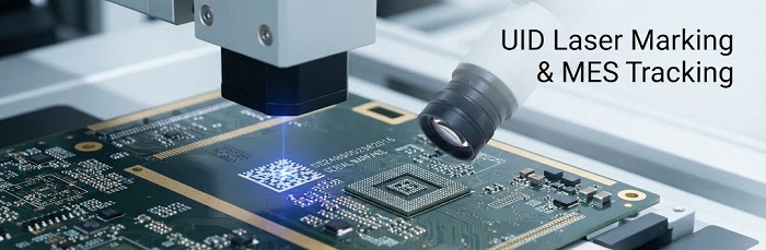
A Smart MES with UID-level traceability and laser marking ties every subsequent event on the board back to a single serial number established at the start of assembly. For an ATE interface board, the practical record typically includes:
• Serial number and assembly date, laser-marked at the point of build, not added later on a paper traveler
• Solder paste and ball lot numbers, so a lot-level solder issue can be traced across every board that used it
• Reflow profile identifier, referencing which oven program and profile version the board ran through
• Inspection results, including 3D SPI paste-volume data, 3D AOI placement results, and any escalation to off-line X-ray for BGA voiding
• Warpage measurement data, captured at post-placement and post-reflow checkpoints
• Rework history, including the reason for each event, the fixture used, and the technician or workstation involved
None of these fields is useful in isolation. Their value comes from being bound to the same UID across the board's entire life — from first assembly through every subsequent rework — so a question asked years into field service can still be answered against the original build data.
How Do Customers Use This Record for Predictive Maintenance and Replacement Decisions?
Probe-cycle degradation is a curve, not a fixed number — cycle life depends on probe type, contact force, DUT socket design, and application-specific factors, so no single figure applies across board designs. What a UID-linked build and rework record does provide is the ability to correlate observed field degradation against a specific board's actual history, rather than a generic assumption.
As an illustrative example only: if a customer reports intermittent contact resistance on a board pulled after a period of service, a traceable record lets the engineering team check whether that board's original inspection data showed a borderline reading, whether it has already been reworked once for a related issue, and whether other boards from the same build lot show a similar pattern. That comparison — not a proprietary failure-rate statistic — is what turns a single field complaint into a decision about whether to replace one unit or flag a lot for preventive attention.
This is the same logic behind MES traceability architecture built for IEC-regulated industrial electronics: the goal isn't predicting failure from statistics that don't exist for a given board population — it's making sure the data needed to make that judgment call is retrievable when the question comes up.

How Does This Connect to IPC-A-610 Class 3 Rework Documentation Requirements?
ATE interface boards — probe cards, DUT boards, load boards — are typically held to IPC-A-610 Class 3 acceptance criteria, the classification reserved for products where continued performance and reliability are essential and downtime is not acceptable. Class 3 rework requirements extend beyond simply fixing a defect; they require documentation of what was found, why rework was performed, what method was used, and what the post-rework inspection confirmed.
MES traceability is what makes that documentation persistent rather than paper-based and easy to lose. Every rework event is logged against the same UID as the original build, with fields for the failure mode that triggered the rework, the method or fixture used during the rework itself, and the inspection result that closed it out. For a board with multiple rework cycles over its service life, this produces a chronological record an auditor or customer engineering team can review without reconstructing history from separate paper travelers.
What Fields Should Be in Your ATE Board's MES Traceability Record?
At minimum, a lifecycle-tracking record for an ATE interface board should include:
• Laser-marked UID and assembly date
• Solder paste / solder ball lot numbers
• Reflow oven and profile identifier
• 3D SPI and 3D AOI inspection results
• X-ray inspection results, including oblique-angle data where applicable
• Post-placement and post-reflow warpage measurements
• Rework event log: date, cause, method, fixture, technician
• Post-rework inspection result for each rework event
• Component lot traceability for any parts replaced during rework
Get Traceability Right Before Your Next ATE Board Build
If you're specifying a new ATE interface board program or evaluating a supplier switch for an existing one, the traceability schema matters as much as the assembly process itself — it's what your engineering team will rely on months or years after the board ships. Submit your ATE project's traceability requirements for a project evaluation, and our team will walk through how your board's UID record would be structured before production begins.
Helpful Resources
● BGA Void Rate Acceptance Reference: IPC-7095D & IPC-A-610 Class Criteria


