



Chip-on-board assembly is well understood on rigid FR-4. The die is attached directly to the substrate, wire bonded, and encapsulated in a single protected package. Moving that same process onto a flexible or rigid-flex substrate does not change the fundamental sequence, but it does change the assumptions the process is built on. A rigid board does not move once it leaves the line. A flex or rigid-flex board is designed to move, and that difference has direct consequences for how a bonded die and its wire bonds behave over the life of the product.
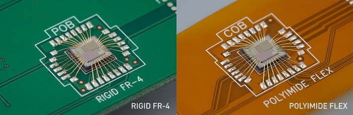
Why Flex/Rigid-Flex Introduces Additional Considerations
On a rigid board, the die attach site and the wire bonds are effectively fixed in space after encapsulation. On a flex or rigid-flex circuit, the same components may sit near, or occasionally within, a region of the board that is expected to bend, fold, or flex repeatedly in service. Polyimide and other flexible substrate materials also have different thermal expansion and stiffness characteristics than rigid laminate, which affects how stress is transmitted to the die attach layer and to the wire bonds during both assembly and field use. This is not a reason to avoid COB on flexible substrates; it is a reason to treat the die location, the bond geometry, and the encapsulation as design variables rather than defaults carried over from a rigid-board layout.
Mechanical Stress on the Bonded Die and Wires During Flexing/Forming
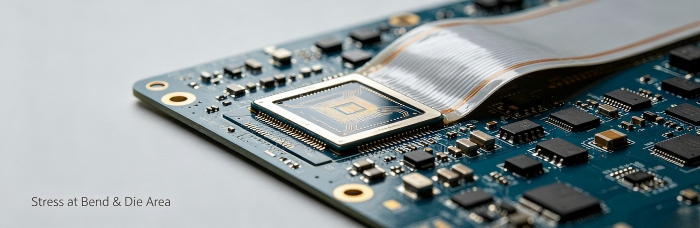
The die itself is rigid and brittle relative to the substrate around it. When a flexible circuit is formed into its final shape, or flexes repeatedly during use, any bending that occurs close to the die attach area can place localized stress on the die, the die attach material, and the fine wire bonds connecting it to the substrate. Wire bonds are particularly sensitive to this kind of mechanical loading, since repeated flexing near a bond can fatigue the wire or loop over time. The same is true during the forming step itself, when a flex or rigid-flex circuit is bent into its installed configuration; if that bend radius is tight and close to the die, the assembly can see meaningful stress even before the product is put into service. Understanding where flexing will occur, and how close that is to the bonded die, is a core part of planning a COB build on flexible circuit die attach.
Encapsulation Material Choices
Encapsulation on a rigid board is primarily about environmental and mechanical protection of the die and wire bonds. On flex and rigid-flex substrates, the encapsulant also has to accommodate the fact that the substrate underneath it may flex, while the encapsulant itself is typically a much stiffer material once cured. A hard, rigid glob-top over a flexible circuit effectively creates a stiff island on a flexible base, which shifts the mechanical stress to the boundary between the encapsulated area and the surrounding flex material. Material selection, cure profile, and the size and shape of the encapsulated area all factor into how well that boundary tolerates flexing, and these choices are generally made in consultation with the encapsulant manufacturer's guidance for flexible applications rather than assumed from rigid-board practice.
General Design Guidance
A few general principles are worth keeping in mind early in layout, well before assembly begins:
Where the mechanical design allows it, locating the die attach site on a rigid or stiffened area of a rigid-flex assembly, rather than in a dynamic flex zone, removes a significant source of stress on the die and wire bonds. Where the die must be placed near a flex region, keeping adequate distance between the bonded area and the bend line, and avoiding tight bend radii close to the die, reduces the stress transmitted during forming and subsequent use. Encapsulation should be sized to protect the die and bonds without extending unnecessarily into areas of the board that are meant to remain flexible. These are conceptual starting points; the right approach for a given rigid-flex chip on board design depends on the specific mechanical requirements of the application and should be worked through with your assembly partner during design review.
If you are evaluating chip-on-board assembly on a flexible or rigid-flex circuit, get in touch with PCBCart to discuss your design and how it can be supported.
Help Ressources
• High-Reliability Rigid-Flex PCB for Medical Life Science Instrumentation
• Free PCB DFM Check and Checklist for PCB Assembly
• Rigid Flex PCB, Semi Flex PCB, Rigid Flex Board — Fabrication Capabilities


