



Send the richest format that your fabricator’s production CAM system imports natively, at the exact revision your design tool exports, without a conversion step in between. For most boards today that is still a clean Gerber X2 set with Excellon drill data, a drill tool list and an IPC-D-356 netlist. ODB++ and IPC-2581 earn their keep on dense multilayer, HDI and turnkey work, but only when both ends of the handoff have been proven on a real job. In every case, a complete, internally consistent package tied to one design revision matters more than the name of the format.
That answer sounds simple, yet format choice is where many first builds lose days. A designer exports an intelligent dataset because the CAD menu offers it; the factory’s front end quietly converts it back to layer images; the layer order is guessed; and an engineering query lands in the designer’s inbox two days later. This guide explains what each format actually carries, how fabricators receive and check it, which format fits which kind of board, and how to assemble a data package that clears CAM review the first time.
Key Takeaways
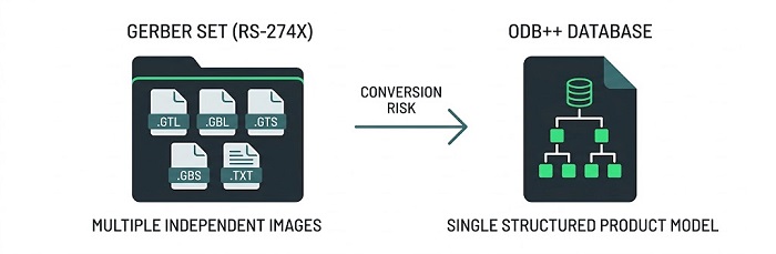
• Gerber describes images, one layer per file. ODB++ and IPC-2581 describe the product: layers, holes, nets, components and stackup in one structured dataset.
• Modern Gerber is not “dumb.” Gerber X2 attributes and a Gerber Job file can carry layer function, pad roles, the CAD netlist and the build specification, but only if you turn them on.
• An intelligent format pays off only when the receiving CAM path reads it natively. A converted import can lose exactly the information you sent it for.
• No format replaces a clear statement of requirements. Impedance targets, IPC class, tolerances and special processes still have to be written where a person will read them.
• Whatever you send, generate every file from the same release, check it in a viewer that did not create it, and name one dataset as the governing reference.
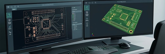
What Does a Fabricator Actually Need From Your Data?
Before comparing formats, it helps to be clear about the job a data package has to do. When your files arrive, a CAM engineer has to answer six questions before any tooling is made. Every format is simply a different way of answering them, and the formats differ mainly in how many answers they carry natively and how many you must supply in separate files.
| Question CAM must answer | Typical source of the answer |
|---|---|
| What should be imaged on each layer? | Copper, solder mask, legend and paste artwork |
| Where are the holes, how big are they, and are they plated? | Drill data plus a drill tool list, with plated and non-plated holes separated |
| What is the shape of the board? | Board outline (profile) and any cut-outs, slots or routed features |
| In what order do the layers stack, and what are they made of? | Stackup definition: layer order, dielectric thicknesses, copper weights, materials |
| What is supposed to be connected to what? | Netlist, used for bare-board electrical test and for checking artwork against design intent |
| What is special about this board? | Impedance targets, finish, tolerances, IPC class, via treatment, markings and other notes |
A package that answers all six without contradiction is buildable. A package that leaves one unanswered, or answers it twice with different values, becomes an engineering query. Keep this frame in mind as you read the format descriptions below; it is the clearest way to see what each one adds.
What Is Gerber, and Why Is It Still the Default?
Gerber is an open, ASCII-based vector format that describes one two-dimensional image per file. It began life as the command language for photoplotters, which is why its core instructions are still “draw,” “move” and “flash an aperture.” A typical fabrication set contains one file per copper layer, one per solder mask, one per legend layer, a profile file and, usually, separate drill files in Excellon format. If you want the background on how the format evolved from photoplotter control to modern CAM input, our guide to Gerber extended files covers the history in detail.
From RS-274D to Gerber X3
The format has passed through several generations, and the differences matter when you configure an export:
• RS-274D (Standard Gerber) stored coordinates and aperture numbers but left the aperture shapes in a separate, informally agreed file. It has been formally revoked by the specification owner, and most fabricators no longer accept it. If your tool still offers it, do not use it.
• RS-274X (Extended Gerber, often called X1) embeds aperture definitions inside each file, so every layer file is self-contained. This is the baseline that virtually every CAM system in the world reads.
• Gerber X2, introduced in 2014, adds standardized attributes to the same files. A file can declare its own function (top copper, bottom solder mask, profile), pads can be tagged as SMD pads, via pads or fiducials, and objects can carry the CAD net name. X2 is backward compatible: a CAM system that does not understand the attributes simply ignores them.
• Gerber X3 extends the same idea to assembly by adding component information such as reference designators, footprints and part numbers.
• The Gerber Job file (.gbrjob) is a small JSON companion that carries no artwork at all. Instead, it can describe the board build: overall thickness, copper layer count, materials, surface finish and the stackup itself. It is one of the most underused files in PCB design.
Where Gerber is strong, and where it is weak
Gerber’s great advantage is universality. Every fabricator can read it, every EDA tool can write it, and free viewers exist on every platform, so a designer can inspect exactly what the factory will see. Its weakness is fragmentation. In a plain RS-274X set, layer order is implied by file names, drill data lives in a different format with its own units and zero-suppression settings, and connectivity is absent unless you add a separate netlist. Each of those separations is a place where two files can disagree.
X2 attributes and a job file close many of those gaps, which is why “Gerber versus intelligent formats” is a less dramatic contrast than it once was. The catch is that both ends must cooperate. The exporter has to be configured to write the attributes, and the receiving CAM system has to use them. If either side does not, the package behaves like plain RS-274X.
What Is ODB++, and What Does It Add?
ODB++ was created by Valor in the mid-1990s as a database for moving PCB designs into manufacturing, and it is now maintained within the Siemens electronics ecosystem, with free viewers and export interfaces available. Instead of a folder of independent images, an ODB++ job is a hierarchical directory structure, usually compressed into a single .tgz archive for transfer. A central matrix defines every layer and its role and order, while separate sections hold layer features, drill and rout spans, the netlist, component placement and attributes.
The practical difference shows up in what CAM no longer has to infer. In a Gerber viewer, a rectangular copper shape is just a shape; nothing tells you whether it is a component pad, a test point or a piece of a copper pour. In ODB++, that same feature is explicitly a pad, on a named net, belonging to a specific component pin, and a drill span records exactly which layers a via connects. Layer order is defined rather than guessed. For a board with buried vias or several sequential laminations, that removes a whole category of ambiguity.
In 2020 the format was broadened into a family, with ODB++Design for design-to-manufacturing transfer joined by ODB++Process and ODB++Manufacturing for factory-floor data. For a designer sending a board to a fabricator, ODB++Design is the part that matters.
The trade-offs
• Governance. The specification is published and free to use, but it is controlled by a single company rather than a standards body. Some organizations treat that as a supply-chain consideration, especially for long-life products.
• Version alignment. An ODB++ export from a recent EDA release may use features that an older CAM importer does not recognize. Unsupported content can be dropped without an obvious error, which is worse than a clear rejection.
• Inspection. ODB++ is harder to eyeball than Gerber. You need an ODB++-capable viewer to confirm what you are sending, and many designers skip that step.
What Is IPC-2581, and Why Does “Open” Matter?
IPC-2581, also known as IPC Digital Product Model Exchange (DPMX), is an open standard maintained by IPC and supported by an industry consortium of EDA vendors, fabricators, assemblers and OEMs. It describes the product in a single structured XML file that can include copper artwork, the full stackup with materials and dielectric data, drill and rout information, the netlist, component placement, the bill of materials and assembly and test information. The original standard was published in 2004; Revision C, released in 2020, expanded support for modern constructions and added a mechanism for exchanging DFM feedback between manufacturer and designer in the same format.
Conceptually, IPC-2581 solves the same problem as ODB++. The difference is ownership. Because the IPC-2581 standard is managed by an industry body rather than one vendor, it appeals to organizations that want vendor-neutral data, long archive life and freedom to move work between suppliers and tools. Our overview of the IPC-2581 standard explains its structure in more depth.
The trade-offs
• Uneven intake support. Adoption has been strongest among larger, automation-focused manufacturers. Many fabricators can view or convert IPC-2581, but fewer use it natively as the source for production tooling.
• Revision and profile mismatch. An IPC-2581 file is valid against a specific revision of the schema, and exporters let you choose which data sections to include. A file can be perfectly valid XML and still omit something the receiver needs, or express it in a way the receiver interprets differently.
• Richer data, wider exposure. A single file that contains the netlist, BOM and stackup reveals more of your design than a set of artwork files. Decide which sections a given supplier actually needs.
How Do Gerber, ODB++ and IPC-2581 Compare Side by Side?
The table below compares typical capabilities. It describes what each format can carry, not what a particular exporter writes or a particular supplier reads; that has to be confirmed for each handoff.
| Attribute | Gerber (RS-274X / X2 / X3) | ODB++ | IPC-2581 |
|---|---|---|---|
| Data model | Layer images, optionally with attributes | Hierarchical product database | Single structured XML product model |
| Typical delivery | Multiple files zipped together | One compressed directory tree (.tgz) | One XML file, sometimes compressed |
| Layer order and function | Implied by file names in X1; declared by attributes in X2 | Defined in the job matrix | Defined in the stackup section |
| Stackup and materials | Only via a Gerber Job file or separate drawing | Can be embedded | Can be embedded, including dielectric data |
| Drill data | Usually separate Excellon files | Integrated, with layer spans | Integrated, with layer spans |
| Netlist | Separate IPC-D-356 file, or CAD net attributes in X2 | Integrated | Integrated |
| Components and BOM | Separate files, or component layers in X3 | Integrated | Integrated, including BOM |
| Governance | Open specification published by Ucamco | Published specification controlled by Siemens | Open IPC standard with industry consortium |
| Human review | Easy; free viewers everywhere | Needs an ODB++ viewer | Needs an IPC-2581 viewer |
| Fab acceptance | Universal | Broad among established fabricators and EMS providers | Growing; confirm per supplier |
| Main risk | Missing or mismatched companion files | Exporter/importer version mismatch | Revision or content-profile mismatch |
Why “Can My Fab Build From It?” Is the Real Question
Debates about formats tend to focus on which one is technically superior. For a specific build, that is the wrong question. What matters is what happens to your data in the first hour after it arrives at the factory, and there are three common paths.
1. Native import. The CAM system reads the format directly and uses its content, including nets, spans and stackup, to drive tooling and DFM checks. This is where intelligent formats deliver their full value.
2. Import with conversion. The front end converts the incoming file into its own internal format or back into layer images. Whatever the converter does not understand may be discarded, and the netlist or pad roles you carefully exported may never reach the engineer.
3. Manual reconstruction. The engineer views the dataset and rebuilds the job from it, often referring back to a Gerber set or drawing. This is slower than receiving a clean Gerber package in the first place.
A sophisticated format sent down path 2 or 3 can produce a worse outcome than a well-prepared Gerber X2 package, because the failures are quiet. Before you change formats for an important build, ask your fabricator these questions in writing:
• Which formats, and which versions or revisions of each, does your production CAM system import natively?
• Do you use the incoming file directly, or convert it before tooling? If you convert, what is lost?
• Will you still want a Gerber set or a fabrication drawing alongside the intelligent dataset?
• If the imported result conflicts with our drawing or another file, will you stop and ask, or proceed?
• Does changing format on a repeat part number trigger a new engineering review?
Clear, specific answers to those five questions are worth more than any general rule about which format is best.
Which Format Should You Send for Your Board?
With the receiving side in mind, the choice usually follows from the board and the supply-chain situation. The scenarios below are starting points, not absolutes; a supplier’s confirmed capability always overrides them.
| Your situation | Recommended package | Why |
|---|---|---|
| Simple 2–4 layer prototype | Gerber X2 + Excellon drill + drill tool list | Universal acceptance and the fastest path through any CAM queue |
| Multilayer board with controlled impedance | Gerber X2 + job file + netlist, or ODB++/IPC-2581 if natively supported; plus a stated stackup and impedance table | Layer order and impedance intent must travel with the data, not in a separate email |
| HDI, blind/buried vias or sequential lamination | ODB++ or IPC-2581 where natively supported; otherwise Gerber X2 with explicit drill-span files and a drill table | Via spans are the easiest thing to misread from flat images |
| Fabrication and assembly with one partner | ODB++ or IPC-2581 if the partner confirms native use; otherwise Gerber X2/X3 plus BOM and centroid | One product model can feed fabrication, stencil, placement and test programming |
| Several fabricators or second sourcing | Gerber X2 package as the common baseline | The format every supplier can read reduces qualification effort |
| First order with a new fabricator | Gerber X2 package, then ask what else they accept | Never make a first build depend on an untested import path |
| Long-life or regulated product needing archives | IPC-2581 archived alongside a Gerber X2 reference set | Open governance and a universally readable fallback both age well |
What Belongs in a Complete Data Package?
Whichever route you take, the format is only part of the release. Most CAM holds come from what is missing around the artwork rather than from the artwork itself.
If you are sending Gerber
1. Artwork for every layer: each copper layer, solder mask, legend and, if the same partner makes your stencil, paste layers. Name files so the layer order is unambiguous without reading an email.
2. A single board profile: one closed contour on its own layer, not duplicated on silkscreen or mechanical layers.
3. Drill data in Excellon format: plated and non-plated holes in separate files, with units and zero-suppression stated, generated with the same origin and scale as the artwork.
4. A drill tool list or drill table: finished hole sizes, quantities, plating status and tolerances in readable form. The drill file alone does not always make tool sizes unambiguous.
5. An IPC-D-356 netlist: this lets bare-board electrical test compare the finished board against your design intent rather than against artwork derived from the same possibly flawed source.
6. A Gerber Job file: it takes moments to generate in most modern EDA tools and answers many of the questions a CAM engineer would otherwise send you.
7. A requirements statement: stackup, finished thickness, material, copper weights, finish, impedance targets, IPC class and any special processes such as via filling or back-drilling.
If you are sending ODB++ or IPC-2581
The intelligent dataset absorbs most of items 1 to 6, but not automatically and not always completely. Before release, open the export in an independent viewer and confirm that the layer count and order, drill spans, outline and net count match your design. Then add what the dataset may not reliably carry: the requirements statement, any acceptance criteria and, if your supplier asks for it, a Gerber reference set generated from the same release. The structured layer stackup inside an intelligent format is only useful if it is the stackup you actually want built; if it is a target rather than a frozen construction, say so.
Always include a revision manifest
A short readme listing every file, its purpose, the design revision, units and release date costs a few minutes and prevents the most common quote and CAM delay of all: files from two different points in the design history arriving in the same archive. Before you zip the package, delete old exports, test outputs and any hidden layers you did not mean to send.
Can You Send Two Formats at Once?
Sending both a Gerber set and an ODB++ or IPC-2581 dataset is a common safety net, particularly for a first build with a new supplier. It works well under one condition: the package must state which dataset governs production and what the other one is for, whether that is a cross-check, a fallback or a reference only.
Generate both from the same release in the same session, compare them yourself before sending, and ask the fabricator to stop and query any disagreement rather than choosing whichever version looks right. Two datasets with no declared hierarchy do not double your safety. They transfer a design decision to someone at the factory who cannot know your intent.
How Does Your Format Choice Affect Assembly and Test?
Fabrication is only the first consumer of your data. If the same partner also builds the assembly, the data package feeds stencil design, pick-and-place programming, optical inspection set-up and electrical test, and each of those steps has its own appetite for information.
With a Gerber route, assembly needs separate inputs: paste layers for the stencil, a centroid or pick-and-place file with reference designators, X/Y positions, rotation and board side, a BOM with manufacturer part numbers, and an assembly drawing showing polarity and any parts that must not be populated. Each of these is generated separately, so each is another chance for a revision to drift. Gerber X3 narrows that gap by carrying component data alongside the artwork, although assembly-side support for X3 is less mature than fabrication-side support for X2.
ODB++ and IPC-2581 carry component placement and, in IPC-2581’s case, BOM content inside the same model as the copper. When a partner uses that content natively, rotation conventions, side assignments and footprint origins no longer have to be reconciled by hand, which is one of the quieter but more valuable benefits of an intelligent format on dense assemblies.
Two cautions apply in every case. First, the sourcing BOM is a commercial document as much as a technical one: approved alternates, customer-supplied parts and do-not-populate decisions often change after layout is frozen, so confirm that the BOM embedded in an intelligent export is the same one you approved for purchasing. Second, test data such as fixture requirements, test limits and firmware versions changes independently of the board geometry and normally needs its own controlled documents, whichever format carries the layout.
What Should Buyers Ask When Comparing Suppliers on Data Intake?
For procurement teams, “we accept ODB++” or “IPC-2581 supported” on a supplier website is not enough to compare quotes fairly. Those phrases can mean native production import, viewing only, or conversion by hand. When you request quotes for the same part number from several suppliers, make the data question explicit:
• Name the governing dataset. State which format and revision you are sending, and ask each supplier to confirm, in the quotation, which files they will actually use to build.
• Ask about conversion. If a supplier converts your data, ask what is retained, what is discarded and whether they will send the converted result back for your approval.
• Agree on the review output. A DFM review should end with a written list of questions or proposed changes. Ask what inputs the review uses and what you will receive.
• Define the stop rule. Ask whether the supplier holds the job when files conflict, and who on your side is authorized to resolve the conflict.
• Check repeat-order behaviour. Find out how the supplier archives the released data and whether a reorder uses that archived package or requires a new submission.
• Agree on data handling. Richer datasets reveal more of your design. Confirm how files are stored, who can access them and how long they are retained.
Asking these questions up front keeps price comparisons honest, because a low unit price that excludes data preparation, conversion or resubmission time is not really the lowest cost.
What Goes Wrong at CAM, and How Do You Prevent It?
The table below lists the failure modes that most often stop or misdirect a job, which formats they affect and how to prevent them before export.
| Failure mode | Most exposed format | What happens | Prevention |
|---|---|---|---|
| Layer order given only in file names | Gerber X1 | Inner layers built in the wrong sequence; impedance reference planes shift | Enable X2 attributes, add a job file and state the stackup explicitly |
| Open or duplicated board outline | All | Routing program cannot be generated; job placed on hold | One closed contour on one layer; zoom to every corner in a viewer |
| Drill file at a different scale, origin or unit | Gerber | Holes misregistered against pads | Export drill and artwork in one session with matching settings; overlay them before sending |
| Plated and non-plated holes combined | Gerber | Mounting holes plated, or plated holes left bare | Separate PTH and NPTH files and mark plating in the drill table |
| Painted pads instead of flashed apertures | Gerber | Pads lose their identity; DFM and stencil generation suffer | Check export settings; confirm pads render as flashes in a viewer |
| Mixed revisions in one archive | All | Netlist, drill or BOM disagree with artwork | Generate everything from one release; include a manifest |
| Unsupported objects dropped on import | ODB++, IPC-2581 | Missing features with no obvious error | Confirm importer version; review the supplier’s import warnings |
| Conversion back to images on intake | ODB++, IPC-2581 | Netlist and pad intelligence never reach the engineer | Ask how the file is used; send a clean Gerber X2 set if it will be converted anyway |
How Do You Validate an Export Before It Leaves Your Desk?
Exporting manufacturing data and exporting it correctly are not the same thing. An ODB++ archive that opens without error can still contain a drill layer at the wrong scale, and a Gerber set that looks perfect in your CAD tool can be missing an inner layer. A ten-minute check before release catches most of these problems:
1. Open the output in a viewer that did not produce it. Reviewing inside the same CAD tool only proves that the tool agrees with itself.
2. Count the layers and compare that number with your intended stackup. Confirm polarity on any negative plane layers.
3. Overlay drill data on copper and check registration at several points, including the board corners.
4. Confirm the outline is a single closed shape and that no stray mechanical or note layers sit on top of it.
5. Compare the netlist in the package with your design netlist, or check the net count in an intelligent-format viewer.
6. Verify that every file in the archive carries the same revision identifier, then record what you sent.
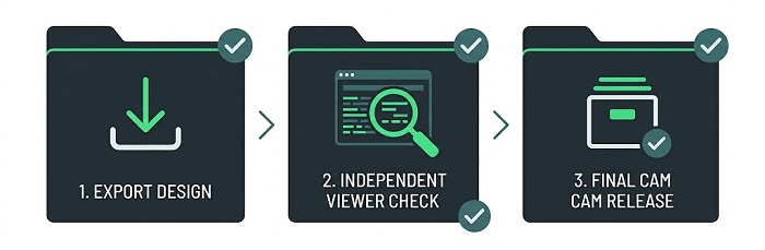
This matters doubly because your fabricator’s checks are only as good as the reference you provide. Bare-board electrical test can find opens and shorts in the finished board, but it can only detect a design error if the test is built against an independent and correct statement of connectivity.
How Should a Team Move From Gerber to ODB++ or IPC-2581?
If your organization decides to adopt an intelligent format, treat it as a process change rather than a checkbox in an export dialog. A practical migration path looks like this:
1. Choose a known-good board that already built successfully from Gerber and that exercises your typical features: the layer count, via types and outline complexity you use most.
2. Export it in the new format from the CAD release and settings you will use in production, and save those settings as a controlled template.
3. Review the export in an independent viewer and record the counts that matter: layers, holes by size, nets and components.
4. Send the dataset to each intended supplier and ask them to import it through their production CAM path, not a demonstration viewer, and to return any warnings.
5. Compare their imported result with the Gerber-based job that already built correctly. Resolve every difference before the new format is used alone.
6. Run at least one build in parallel, with the Gerber set as the declared reference, before making the intelligent dataset the governing source.
7. Repeat the qualification whenever the EDA version, the export template or the supplier’s CAM system changes significantly.
This takes a little effort up front, but it turns an unknown import path into a known one, and that is exactly what makes the richer format worth having.
Submitting Fabrication Data to PCBCart
At PCBCart, our fabrication intake is built around the format every design tool can produce and every engineer can inspect. Here is what that means in practice when you prepare a package for us:
• Gerber RS-274X is our preferred format. Gerber X2 output is fully compatible with this route, since it is RS-274X with attributes added. We do not accept RS-274D. We can also work from native Protel (.PCB/.DDB, please tell us the program version) and Eagle (.BRD) files, although exporting Gerber yourself keeps you in control of exactly what we see.
• Drill data needs a tool list. Please provide an NC Excellon drill file together with a drill tool list. The tool list is the item most often missing from first-time submissions.
• The order form governs board construction. Specifications entered on our online order form, such as thickness, copper weight, solder mask and finish, define the build. Separate readme or specification files are not used to set those parameters, so put any non-standard requirement, including impedance control targets, in the Special Requirement Note when you order.
• Custom stackups are handled through our Standard PCB service. We build multilayer boards from 4 to 32 layers. Our prototype service uses default stackups; if your design depends on a specific construction, order it as a Standard PCB and we will confirm the stackup with you.
• Every board is electrically tested. We perform 100% electrical test on the boards we manufacture, using flying probe or bed-of-nails fixtures in line with IPC-9252, and our engineers carry out a DFM review of your files before production begins.
If your design team works natively in ODB++ or IPC-2581, keep that dataset as your engineering reference, export a Gerber RS-274X package and Excellon drill data from the same release for production, and mention the intelligent dataset in your order notes. Our engineers can then advise, project by project, whether it can help with cross-checking. As an IATF 16949-certified manufacturer serving industrial, life-science and test-equipment customers, we would rather confirm a question before tooling than discover a data conflict on the production floor.
Frequently Asked Questions
Does my fabricator need to “support” Gerber X2 for me to use it?
No. X2 is designed to be backward compatible, so a CAM system that does not understand the attributes reads the files exactly as it would read RS-274X. Turning X2 on costs you nothing and benefits any receiver that does use the attributes. The only caution is not to rely on attributes alone to communicate something critical, such as layer order, unless your fabricator has confirmed that it reads them.
Is a Gerber Job file still worth generating if my fabricator uses an online order form?
Yes, but understand its role. If the fabricator’s order form governs construction, the job file will not override what you enter there. It is still a valuable cross-check, because a CAM engineer who sees a job file stating eight layers and 1.6 mm can immediately spot an order entered as six layers. Make sure the two never disagree.
Will an ODB++ file from a newer EDA release open in an older CAM system?
Often it will open, which is precisely the risk. Content that the older importer does not recognize may be skipped rather than rejected. If you have recently upgraded your design tool, ask your fabricator which ODB++ version their importer supports and, where possible, export to that version.
Does IPC-2581 expose more of my intellectual property than Gerber?
It can, because a full IPC-2581 file may contain the netlist, BOM, component data and stackup in one place. Most exporters let you choose which content to include, so a bare-board fabricator may not need the BOM at all. Decide what each supplier genuinely needs, and handle the rest under your normal confidentiality agreements.
If I switch formats between prototype and production, do I need a new DFM review?
You should expect one. Even when the design is unchanged, a different format means a different import path and potentially different interpretation, so most fabricators treat it as a new submission. Plan for a full review on the first order in the new format rather than assuming repeat-order turnaround.
Why not just send the native CAD file and let the fabricator export it?
Because you lose control of the most important step. The receiver needs a compatible tool and version, may use different export settings, and has no reliable way to tell which parts of the design are released and which are work in progress. Native files are valuable for archiving or for handing a design to another design team, but the manufacturing reference should be a neutral package that you generated and checked yourself.
Can a fabricator recreate missing drill or outline data from the copper layers?
Sometimes, but you should never rely on it. Hole positions can be inferred from pad centres, but hole sizes, plating status and intended tolerances cannot be inferred reliably, and an inferred outline may not match your mechanical design. Missing data should be supplied, not reconstructed.
Ready to Release Your Fabrication Data?
Prepare a clean, single-revision Gerber package with drill data and a tool list, enter your build requirements on the order form, and let our engineers review it before production.
Helpful Resources
• How to Generate Gerber Files Based on Different PCB Design Software
• What File Formats Are Required, and What Happens If My Files Don’t Match?


