



Semiconductor test equipment obsolescence is a structural, not occasional, risk. Automated test equipment (ATE) platforms in semiconductor final test and wafer sort routinely stay in production service for 10 years or more. The PCBA subsystems inside them — pin electronics boards, DUT interface boards, calibration modules — were built with components selected against a much shorter commercial clock. That mismatch between platform lifecycle and component lifecycle is a recurring condition of the ATE segment. It needs to be engineered around, not reacted to.
The Lifecycle Mismatch, Stated Plainly
Semiconductor components used in precision analog and mixed-signal circuits — high-speed DACs/ADCs, precision voltage references, specialized comparators, and application-specific driver ICs — typically follow commercial product cycles measured in a small number of years. Then a manufacturer issues a Product Change Notification (PCN) or End-of-Life (EOL) notice. ATE platforms, by contrast, are capitalized assets. Depreciation schedules and qualification costs push owners toward decade-plus service life. A pin electronics card qualified against a specific comparator IC in year one may still need to be manufacturable — and functionally identical — in year eleven.
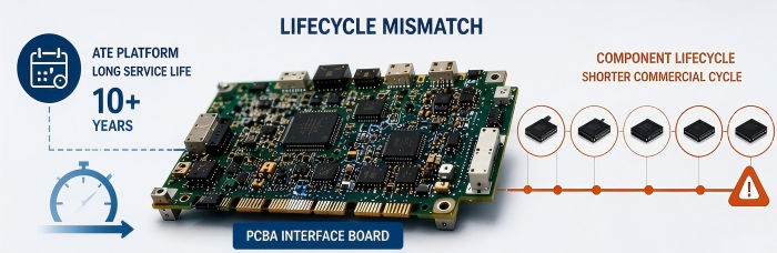
This is distinct from consumer or general industrial electronics, where refresh cycles are shorter and the pressure to match a component's exact AC/DC parametrics is lower. In ATE, the interface board's job is to reproduce timing, voltage accuracy, and noise characteristics that were qualified against the device under test at a specific process node. A substitution that is "close enough" electrically can still fail a correlation study against the original test program.
Four Mitigation Strategies: Semiconductor ATE vs. Medical/Industrial Context
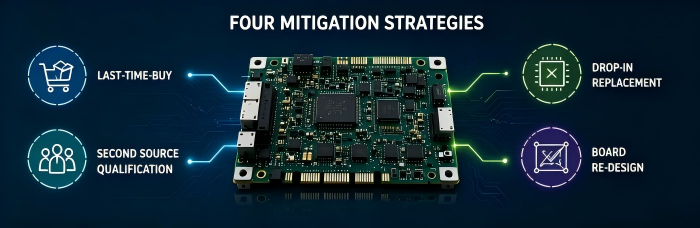
The general obsolescence-management toolkit — last-time-buy, alternate sourcing, form-fit-function substitution, and board redesign — is the same across long-lifecycle electronics segments. What differs is which strategy carries the least risk in a given domain. In our earlier discussion of obsolescence management for life sciences instrumentation, the emphasis sat on regulatory traceability: a substitution had to be defensible inside a Design History File, and requalification effort was driven largely by documentation burden. Semiconductor ATE shifts that weighting toward electrical correlation risk instead of documentation risk.
Last-Time-Buy (LTB) Sourcing
This is the default first response and remains the lowest-disruption option in both domains. For ATE, the constraint is less about warehousing cost and more about date-code and storage-condition control for moisture-sensitive or precision analog parts held over a multi-year horizon. A large LTB buy that degrades in a warehouse solves nothing.
Approved Alternate / Second-Source Qualification
In medical and general industrial PCBA, an alternate part with matching form-fit-function is often acceptable once documentation is updated. In ATE, an alternate must be re-verified against the test program's correlation data — not just the datasheet. Two parts with identical published tolerances can still produce different guard-banding behavior at the tester's operating frequency. This strategy is viable, but it carries a heavier validation tail in the semiconductor context than in medical/industrial use.
Form-Fit-Function (FFF) Drop-In Replacement
This works cleanly when the obsolete part is passive or a simple logic function. It becomes materially riskier on precision analog components, where FFF equivalence on paper does not guarantee equivalence in the test cell's actual signal chain — a distinction that matters far less on, for example, a general industrial power-conversion board.
Interface Board Redesign / Re-Spin
In medical and industrial programs, a redesign is often reserved for true dead-end cases because of the added regulatory re-verification burden. In ATE, redesign is reached for earlier and more deliberately. The interface board is the layer specifically intended to absorb component churn without touching the tester's core hardware or the qualified test program. That tradeoff gets engineered in practice below.
ATE Interface Board Redesign: What a Re-spin Puts at Risk
A DUT interface board or load board re-spin is not a like-for-like layout update. It reopens test compatibility questions that the program owner needs to weigh explicitly:
Test program correlation. Any change to trace length, connector transition, or component placement on signal paths can shift timing skew or insertion loss enough to require re-correlation against the existing test program, not just the new board.
Mechanical interchangeability. ATE interface boards mate to a fixed tester mainframe and prober/handler interface. A redesign has to preserve keep-out zones, connector pinouts, and mounting geometry, or it forces changes further up the test cell.
Calibration continuity. If the redesign touches the calibration or reference circuitry, existing calibration standards and golden-unit references may no longer be valid without a new baseline.
Panelization and fixture rework. Where synthetic stone fixtures were qualified against the prior board outline for warpage control during reflow, a dimensional change on the new board can require re-qualifying the fixture, not just the process recipe.
Coordinated cutover. Because ATE fleets often run many identical testers across a fab or OSAT floor, a board revision typically needs a staged rollout plan rather than a single cutover, to avoid correlation gaps between old- and new-revision boards running the same test program concurrently.
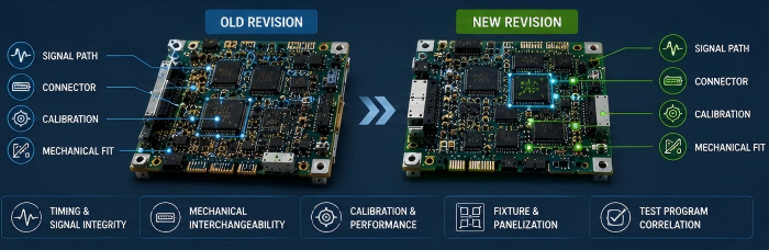
None of these are reasons to avoid redesign — they are the checklist that determines whether redesign is cheaper than continuing to chase a dying part through alternates and LTB extensions.
BOM Health Monitoring as an Early-Warning Methodology
The common failure mode in obsolescence management is not the absence of a mitigation strategy — it's finding out too late to use the cheaper ones. LTB and alternate-sourcing options are available when a part is flagged early; by the time a board is in a stop-ship state, redesign is often the only option left, at redesign cost and schedule.
A practical BOM health methodology, independent of any specific reporting product, generally includes:
Lifecycle status tagging for every BOM line, cross-referenced against manufacturer PCN/EOL notices and distributor lifecycle flags.
Single-source and sole-source identification, since these carry the least buffer against a sudden EOL notice.
Lead-time and allocation tracking for components already showing volatility, as extended lead time is frequently a leading indicator of an approaching EOL announcement.
Prioritization by circuit function, since a flagged passive component on a non-critical rail is a very different risk than a flagged precision reference IC in the signal path.
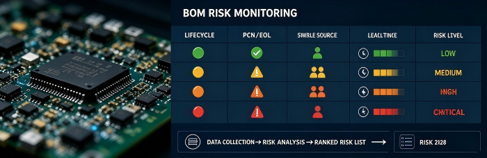
This is a standing engineering discipline applied at BOM release and revisited at defined program checkpoints — not a one-time audit. The output is a ranked risk list an engineering team can act on while LTB and alternate-sourcing options are still open.
Self-Assessment Framework: Is Your ATE Program at Risk?
Before a component obsolescence issue becomes a schedule issue, it's worth running your program's BOM against a short set of questions:
Does every BOM line have a current lifecycle status, or is status only checked reactively when a part fails to ship?
How many BOM lines are single-sourced with no qualified alternate on file?
For precision analog components, has an alternate ever been validated against actual test-program correlation data, or only against datasheet parametrics?
If a redesign became necessary tomorrow, does the mechanical/interface documentation exist to scope it without reverse-engineering the current board?
Is there a defined trigger point — lead-time threshold, PCN receipt, allocation notice — that starts the mitigation process, or does action wait for a stock-out?
A BOM that answers "no" to more than one or two of these is carrying more obsolescence risk than its program owners may realize.
Get a BOM Risk Screening
Submit your ATE program's bill of materials, and PCBCart's engineering team will screen it against current lifecycle status, single-source exposure, and alternate-part availability — then return a ranked risk summary you can act on before the next PCN forces the decision.
PCBCart runs ATE and precision test PCBA on a process stack built for correlation-sensitive builds: 3D SPI and 3D AOI closed-loop inspection, offline oblique-angle X-ray for BGA/QFN voiding, and Smart MES with UID traceability for full build-record lookback — the same process controls that matter when a redesign or alternate-part qualification has to hold up against an existing test program.
[Submit your BOM for a risk review →]
Helpful Resources
• AOI vs. X-Ray Inspection: Which is Right for Your PCB Assembly?
• Free DFM Check
• Components Sourcing
• How to Avoid Counterfeit Electronic Components


