



Chip-on-board assembly places a bare die directly onto a substrate, connects it with fine wire bonds, and covers it with an encapsulant. On a standard rigid PCB, that substrate stays in a fixed shape for the rest of its life. On a flexible circuit board or a flex-rigid PCB, the substrate is designed to bend, fold, or flex, either during installation or repeatedly throughout normal use.
That difference changes the engineering problem at the die level. The die itself is rigid and brittle, the wire bonds are fine and largely unsupported along their length, and the encapsulant has its own stiffness and coefficient of thermal expansion. None of these components can flex the way the substrate around them does. When the substrate moves and the die, wires, and encapsulant don't move with it in the same way, strain concentrates at whatever interface separates the rigid parts from the flexible ones.
This is why COB on flex or rigid-flex needs to be planned as a mechanical system, not just an electrical one. The assembly still has to meet the same electrical and process fundamentals as COB on rigid boards, covered in more detail in PCBCart's article on die attach and wire bonding, but the layout and material decisions carry more weight because the board itself is part of the mechanical loading path.
Why Flex or Rigid-Flex Introduces Additional Considerations
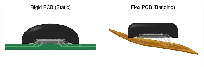
On a rigid board, once reflow and wire bonding are done, the substrate's shape is fixed for the rest of the assembly's life. Mechanical stress on a die-attach joint or a wire bond mostly comes from thermal cycling, and it's relatively predictable and uniform across similar designs.
A flexible circuit board changes that baseline. The whole point of the substrate is that it moves, whether it's formed once into a fixed shape during installation or flexed continuously in service, as in a wearable device or a cable-replacement application. A rigid-flex PCB adds another layer, because it combines rigid sections meant to carry components with flexible sections meant to bend, and the transition zone between the two is its own mechanical detail worth attention.
For COB specifically, this matters because the die and its bonded wires are usually placed close to the substrate surface, with little standoff or mechanical buffering. Whatever bending, twisting, or forming strain reaches that area of the substrate is transferred, largely unfiltered, into the die attach joint and the wire loops sitting right above it.
Mechanical Stress on the Bonded Die and Wires During Flexing or Forming
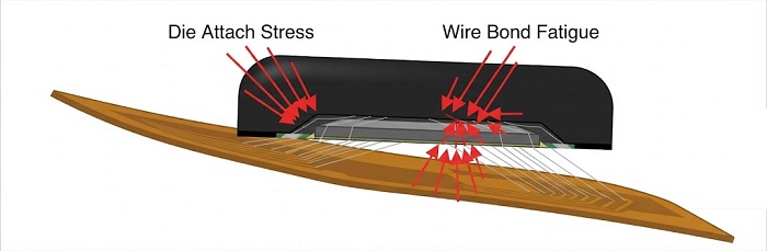
The die attach joint is usually the first thing to feel this strain. A silicon die is essentially rigid at the scale of ordinary bending, so it can't absorb curvature the way the substrate around it can. If a flex zone runs underneath or close to the die, bending strain concentrates at the die's edges and at the die attach interface, and repeated cycles of that strain can lead to die attach delamination, die cracking, or slow fatigue at the joint. The die attach adhesive already has to absorb some stress from thermal expansion mismatch between die and substrate, even on a rigid board, so adding cyclic mechanical strain from flexing gives that same joint two separate stress sources to manage instead of one.
Wire bonds carry a related but distinct risk. Each bond is an unsupported span of fine wire between two anchor points, and its loop height and shape are set specifically to avoid contact with the die edge or neighboring wires. Any additional deflection at the substrate beneath a wire loop changes the effective geometry of that loop, and repeated flexing can fatigue the wire at the bond neck, a known weak point in wire bonding generally. A related failure pattern shows up in wire terminations elsewhere on an assembly: PCBCart's article on solder wicking on wire leads describes how rigid material creeping into a wire section that needs to stay flexible creates a stress riser right at the boundary — a useful way to think about what happens if any part of a wire bond area on flex loses its intended flexibility.
Forming operations deserve separate attention. Bending a flex or rigid-flex circuit into its final installed shape is often a bigger, one-time strain event than anything the assembly sees during years of normal flexing afterward. If the bend radius, fold line, or forming fixture isn't planned with the die location in mind, the forming step itself can be the event that damages a joint that would otherwise have survived normal service.
Encapsulation Material Choices
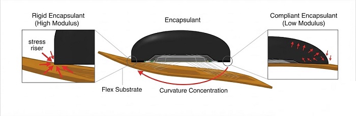
Encapsulation still does the same basic job on flex and rigid-flex that it does on rigid COB: it protects the die and wire bonds from moisture, contamination, and physical contact. What changes is that the encapsulant's mechanical behavior now interacts directly with a substrate that moves.
A stiff, highly cross-linked encapsulant creates a hard-to-flexible transition right at the edge of the glob-top or molded area. That transition is exactly where substrate curvature tends to concentrate, so a rigid encapsulant can effectively narrow the flexible zone and shift bending strain toward its own boundary rather than distributing it more gently. Among the common encapsulant types used across PCBA generally, some formulations are chosen specifically for lower modulus and better elongation — properties that matter more here than on a board that never moves. Coefficient of thermal expansion matching between the encapsulant, die, wire, and substrate also carries more weight, since a flexing assembly is under mechanical load more of the time than a static one.
Handling during assembly is part of the same picture. Encapsulant needs to be dispensed and cured while the substrate is held flat and unflexed, since curing the material in a stressed or bent position can lock residual strain into the joint before the part ever reaches the field. Cure schedule and fixture design matter as much as the resin choice itself.
General Design Guidance
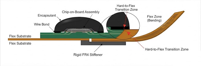
A few principles come up consistently when planning a COB layout on flex or rigid-flex, without pointing to any single fix as sufficient on its own.
Keep the die attach area outside the flex zone where practical. Placing the die on a stiffened section or on the rigid portion of a rigid-flex board, away from the area that's meant to bend, removes most of the dynamic strain problem at its source rather than asking the encapsulant to compensate for it later.
Add local stiffening near the die if relocation isn't possible. A stiffener under or around the die area reduces the curvature that reaches the die attach and wire bond zone, even when the die has to sit closer to a flex region than would otherwise be ideal.
Plan forming operations around the die location, not the other way around. Bend radii, fold lines, and fixture design should keep enough clearance from the die and wire bond area that the one-time strain of forming doesn't exceed what the joint sees over its whole service life.
Treat encapsulation as protection layered on top of a sound layout, not a substitute for one. Material selection for compliance and CTE match helps, but it works best alongside die placement and stiffening decisions that already limit how much strain reaches the die in the first place.
Frequently Asked Questions
Does COB work reliably on flexible PCBs?
Yes, chip-on-board assembly is used on flexible and rigid-flex substrates across consumer electronics, wearables, and other space-constrained products. Reliability depends heavily on keeping the die attach and wire bond area away from active flex zones, or compensating with stiffening and encapsulant selection when that isn't possible.
What causes die attach failure on a flexible substrate?
Repeated bending strain at the die attach joint, on top of the thermal expansion mismatch already present on any COB assembly, can lead to delamination, die cracking, or slow fatigue over time — particularly when the die sits directly over or near a flex zone.
Can standard encapsulants be used for COB on flex?
Standard encapsulants provide the same moisture and contamination protection on flex as on rigid boards, but a highly rigid formulation can create a stress concentration at the boundary of the encapsulated area. Lower-modulus or higher-elongation formulations are often a better match for substrates that flex in service.
Should the die always be kept away from the flex zone?
It's the simplest and most effective approach where the layout allows it, since it removes most of the dynamic strain at the source. When it isn't possible, local stiffening and careful encapsulant selection become more important compensating measures.
If you're evaluating a COB or die-level assembly project on a flexible or rigid-flex substrate, PCBCart's team can help you think through die placement, stiffening, and encapsulation choices for your specific design. Visit PCBCart's PCB Assembly service page to learn more about how we support high-mix, low-volume production needs.
Helpful Resources
· Die Attach and Wire Bonding: How COB Assembly Actually Works


