



Two very different things get called “wicking” in solder joint inspection, and mixing them up leads to the wrong article, the wrong fix, or worse, a defect that gets waved through because it resembles a good sign. One is a wetting indicator that IPC-A-610 explicitly wants to see. The other is a defect that stiffens a wire exactly where it needs to stay flexible, and quietly sets up a fatigue failure that won't show up until the assembly has been vibrating or flexing in the field for a while. This article is about the second one — solder that climbs up a stranded or braided wire lead past its intended termination point.
Two Meanings of “Wicking” — and Why the Distinction Matters
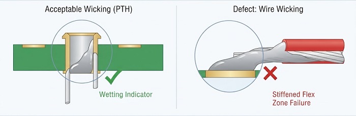
In a plated through-hole barrel, IPC-A-610 Class 3 inspection criteria look for solder wetting climbing the lead on the secondary side of the board — a full barrel with no wicking evidence reads as filled but not necessarily wetted, so the standard treats visible wicking there as a positive confirmation of a sound joint.
On a stranded or braided wire termination, the same physical phenomenon — molten solder traveling up the lead by capillary action — is a defect when it goes past where it should stop. The table below separates the two contexts, because the acceptance direction flips depending on which one is being inspected.
| Context | What “wicking” describes | Acceptance |
|---|---|---|
|
PTH barrel fill (IPC-A-610 Class 3) |
Solder visibly climbing the lead inside a plated hole, confirming the barrel is wetted through and not just mechanically filled |
Desired — evidence of a sound joint |
|
Stranded/braided wire termination |
Solder migrating past the tinned zone into the portion of the wire that the design intends to stay flexible |
Defect — creates a stress riser at the flex boundary |
What This Defect Actually Looks Like on the Bench
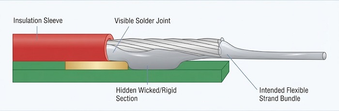
The joint itself is usually the least interesting part — it can look shiny, fully filled, and textbook-correct. The problem sits above the joint, along the wire. Solder that was meant to stop at the tinned termination point continues traveling up the strand bundle by capillary action, often disappearing under the insulation sleeve where it isn't visible without pulling the sleeve back. Externally, the only clue may be a wire that feels noticeably stiffer for a short stretch right at the point where flex is expected — easy to miss on a visual pass, and impossible to catch on standard AOI, since AOI is built to evaluate the joint geometry, not the flexibility of a wire an inch away from it.
Why It's a Reliability Defect, Not a Cosmetic One
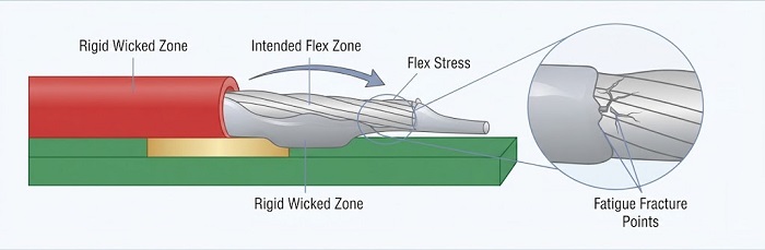
A wire designed to flex has a defined transition point between its rigid, soldered end and its flexible run. Wicking erases that boundary by hardening a section of the strand bundle that the design never accounted for as rigid. Every subsequent flex cycle — from cable routing during assembly, from vibration in an industrial enclosure, from repeated connector mating in field service — concentrates bending stress at the new edge between the stiffened and flexible sections instead of distributing it gradually. Individual strands work-harden and crack at that boundary over repeated cycles, and the wire can fail weeks or months after shipment, well after it passed 100% functional test on the line.
Root Causes
● Oxidized wire or pad surfaces — not because oxidation itself pulls solder upward, but because it resists initial wetting, which pushes operators toward longer dwell time, higher iron temperature, or extra solder to force the joint to wet. That compensating heat and solder volume is what ends up driving the extra capillary travel
● Excessive dwell time or an overly aggressive heating profile during hand soldering, wave, or selective soldering, which drives molten solder further up the strand bundle than the process intended
● Too much solder volume or overly active flux applied during the tinning step itself
● Insulation clearance that leaves more bare strand exposed than the design called for, giving wicking more untinned wire to travel along before it reaches a barrier
What IPC J-STD-001 Actually Requires
J-STD-001's tinning-of-stranded-wire requirements are specific enough to use as a working checklist rather than a vague reminder to “control heat.” In substance: solder wicking must not reach into the section of wire that the design requires to remain flexible; the tinned section itself should show the solder penetrating to the inner strands, with individual strands still discernible rather than fused into a solid blob; and strand-to-strand separation within the tinned area shouldn't exceed roughly one strand diameter or extend past the outer diameter of the wire insulation. Confirm the exact figures against your current revision before writing them into an inspection plan, since DFM review is the right point to lock in insulation clearance and strain-relief geometry before first article, not after.
Why It Gets Missed in Inspection
The defect is frequently hidden under an insulation sleeve, which puts it outside what visible-light AOI can evaluate at all. Catching it reliably means either pulling back a sample of insulation sleeves for direct visual check, or using off-line X-ray on wire-to-terminal joints where the geometry allows it — the same reasoning that makes X-ray necessary for hidden BGA and QFN joints applies here for a different reason: it's not that the joint is under a package body, it's that the defect isn't at the joint at all.
Where This Shows Up Most in Industrial and Life Sciences Assemblies
Any assembly with stranded or braided wire terminating directly to a rigid connection is exposed — connector pigtails, motor and sensor leads, cable-to-board harnesses, and wire-to-terminal joints on through-hole technology boards where a cable terminates straight onto a PTH component pin. It's a particularly relevant failure mode for equipment that flexes or vibrates in normal use — industrial automation enclosures, robotics, and test fixtures with repeated cable movement — where the flex cycle count over the product's service life is exactly what turns a hidden wicking defect into a field return.
Prevention and Process Controls
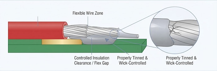
● A controlled pre-tinning process with fixed dwell time and a temperature-controlled solder pot or iron, rather than operator-judged heat and timing
● Flux activity level matched to the wire's finish and gauge, so wetting is complete within the tinned zone without excess capillary carry-over
● Insulation clearance held to the design-specified distance from the termination, so there's a defined mechanical barrier between the flex zone and the tinned zone
● Bare wire storage and handling discipline that prevents oxidation before tinning even begins
● Sample-based teardown or X-ray checks on wire terminations as a defined part of the inspection plan, rather than relying on a visual pass at the joint alone
The takeaway for sourcing and quality teams: a solder joint that looks perfect at the termination doesn't rule out a wicking problem an inch further up the wire. Where flex cycling or vibration is part of the end-use profile, it's worth asking a supplier explicitly how wire terminations are inspected — not just how the joint itself is inspected — since the two are evaluated differently and a defect hidden under an insulation sleeve won't show up in a standard visual pass.
Have a wire termination or cable harness joint you're trying to disposition? Get an Instant Quote for PCB Assembly
Helpful Resources
● How to Check Soldering Defects in PCB Manufacturing?
● Comparison between Through-Hole Assembly (THA) and Surface Mount Assembly (SMA)


