



Medical sensor boards—biochemical analyzers, pressure transducers, optical detection modules—carry a disproportionate share of electrostatic discharge (ESD) sensitive components relative to general industrial assemblies. A single uncontrolled discharge event during handling, placement, or test can degrade a sensor's signal-to-noise characteristics without producing an immediate functional failure, which makes ESD control a upstream reliability discipline rather than a downstream inspection checkpoint.

Why Medical Sensor Boards Are Disproportionately Exposed
Biochemical analysis, pressure, and optical sensing circuits typically combine several component classes that are inherently more ESD-sensitive than standard digital logic:
Precision analog front-ends (instrumentation amplifiers, low-noise op-amps) used to condition microvolt- or nanoamp-level sensor outputs
MEMS-based pressure and optical elements, where thin diaphragms or photodiode junctions can sustain latent damage from discharge energy far below what would destroy a standard logic gate
High-impedance input stages, where even a partial dielectric breakdown shifts bias points and introduces drift that is difficult to detect at final test
The engineering distinction that matters most here is between catastrophic failure and latent (walking wounded) damage. A catastrophic ESD event causes an immediate, testable failure and is caught at electrical test. A latent event partially degrades a junction or dielectric without causing outright failure—the device passes initial test but exhibits accelerated degradation or parameter drift in the field. For medical sensor boards, where output accuracy is the entire point of the product, latent damage is the more consequential risk because it is invisible to standard pass/fail test coverage and only surfaces as measurement drift after deployment.
ANSI/ESD S20.20 as the Governing Framework
ANSI/ESD S20.20 is the industry-standard framework for developing, implementing, and maintaining an ESD control program for equipment and boards containing ESD-sensitive items, and it structures the assembly-floor controls that matter for sensor board production:
Workstation grounding
Ionized air blowers at open-air workstations where insulative materials (packaging, fixtures, connector housings) cannot be reliably grounded, since air ionization is the accepted method for neutralizing static charge on non-conductive surfaces
Constant-monitoring wrist strap systems at manual handling and rework stations, with continuity verified rather than assumed
Personnel and material controls
ESD smocks and footwear where floor-to-body grounding paths are part of the facility's control plan
Static-dissipative or conductive work surfaces, verified periodically rather than installed and forgotten
Ionization coverage
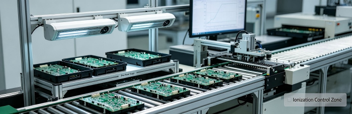
Ionizers positioned at process steps where components are exposed outside of grounded fixtures or shielded packaging—loading trays, manual placement stations, and pre-reflow staging areas
A framework-level control plan only has value if the parts of the process it covers actually match where ESD-sensitive devices are physically exposed. For sensor boards specifically, that means extending controls to any manual staging step, not just the automated placement and reflow line, since manual handling is where grounding paths are most likely to be broken.
IQC-Stage Storage and Transport of ESD-Sensitive Devices
Incoming quality control is the first point in the process where ESD-sensitive medical sensor components require controlled handling, and the practices here set the baseline for everything downstream:
Shielding bag integrity checks on receipt—verifying that moisture-barrier and static-shielding bags have not been compromised in transit, since a punctured shielding layer defeats the purpose of the packaging regardless of what the label says
Segregated storage for ESD-sensitive lots, physically separated from non-sensitive inventory to reduce the chance of a sensitive device being pulled and handled outside a controlled workstation by mistake
Transport in conductive or static-shielding totes between IQC, kitting, and the assembly line, rather than open trays or non-conductive containers
Humidity-controlled storage where components are also moisture-sensitive (a common overlap with MEMS-based sensing elements), since combined ESD and moisture exposure compounds the risk to thin-film and diaphragm structures
The practical failure mode at IQC is not usually a missing procedure—it's a sensitive lot that gets partially unpacked for inspection or sampling and then re-packaged in non-shielding material because the original bag was damaged during the inspection process itself. Controlling for this means IQC handling stations need the same grounding infrastructure as the assembly floor, not a lighter version of it.
MES Traceability for ESD-Sensitive Lot Handling
A Smart MES with UID-level traceability and laser marking provides the mechanism to record ESD-sensitive lot handling as part of the permanent build record, rather than relying on paper travelers that get lost or summarized after the fact. For sensor board builds, the traceability record should capture:
Lot-level ESD sensitivity classification, tied to the component UID at the point of kitting
Workstation and operator association for each ESD-sensitive component at the point of placement, so that if a field return shows drift consistent with latent ESD damage, the specific handling station and time window can be reconstructed

Ionizer and grounding verification logs, where the MES timestamp for a given lot's processing can be cross-referenced against the facility's periodic ESD equipment verification records
This is where ESD control stops being a floor-level procedure and becomes part of the quality record for the board itself. If a customer reports drift in a deployed sensor board months after shipment, a UID-linked traceability record that includes ESD handling metadata is what allows an engineering team to distinguish a genuine ESD-related field issue from an unrelated design or component-lot problem—without that record, every field complaint defaults to a design review with no way to rule ESD in or out.
Latent ESD damage is, by definition, invisible at the point it occurs. The only reliable defense is a control system that assumes exposure will happen at some point in the process and is designed to prevent it at every handling step—not a single inspection gate at the end of the line.
For hardware teams developing biochemical, pressure, or optical sensor boards where signal integrity margins are tight, ESD control needs to be evaluated as part of the assembly process design, not added afterward. PCBCart's HMLV PCBA assembly process incorporates ESD-sensitive handling protocols from IQC through final MES-tracked build record, suited to low-to-mid volume sensor board programs where component-level traceability matters as much as assembly precision.
Ressources utiles
• Essential Standards for Medical PCB Assembly
• Zero-Defect Strategy: Ensuring Long-Term Stability for Medical Electronics
• A Guide to Medical PCB Fabrication and Assembly
• Managing Thermal Reliability in Diagnostic Instrument PCBA


