



An IP67 rating on an outdoor IoT node is not earned by the enclosure design alone. It is won or lost at three assembly steps: gasket compression, cable gland installation, and connector potting. Each step has its own process window, and each fails in predictable ways when that window isn't controlled.
This guide covers those sealing steps only. Mechanical and electrical integration QA for finished units, including fastener audits, harness routing, and functional test, is covered in our separate guide on box-build integration QA.
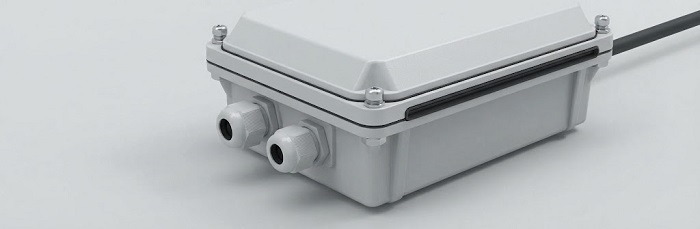
What Do IP65 and IP67 Demand From the Assembly Process?
IEC 60529 defines the IP code. Two ratings dominate outdoor industrial IoT:
IP65: Dust-tight, plus protection against low-pressure water jets from a 6.3 mm nozzle.
IP67: Dust-tight, plus protection against temporary immersion, defined as 1 m for 30 minutes.
The process implication follows from the test. Water jets hit a seal intermittently and from limited angles, so IP65 tolerates small irregularities. Immersion puts static pressure on every seal path at once, for the full duration. A gasket under-compressed in one corner, or a gland clamping at the edge of its range, may pass a hose test and still fail immersion.
IP ratings are type-test results on a design. Production sealing must reproduce the type-tested conditions on every unit.
How Much Should a Gasket Be Compressed?
Compression window
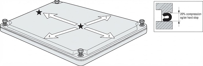
The correct range comes from the gasket supplier's datasheet. Published elastomer seal design guidance, such as the Parker O-Ring Handbook, commonly cites compression of roughly 15–30% for static solid elastomer face seals, depending on cross-section. Closed-cell foam and sponge gaskets are typically designed for higher compression. Treat any general figure as a starting point to confirm against the specific material and durometer.
Compression can fail in two directions:
Too little: Leak paths remain at surface irregularities, molded parting lines, and corners.
Too much: The gasket takes a compression set, cracks, or extrudes from its groove. It often passes initial test and fails after thermal cycling.
Fastener torque and sequence
Compression is only as uniform as the tightening sequence:
Use a cross (star) pattern, never sequential tightening around the perimeter.
Tighten in multiple passes: a snug pass, an intermediate pass, then final torque.
Apply torque values from the enclosure maker's specification. Plastic enclosures with threaded inserts have low limits.
Prefer compression limiters or hard stops in the design, so geometry sets compression rather than operator feel.
Why Do Cable Glands Leak, and How Is Torque Controlled?
Matching gland to cable OD
Every gland has a stated clamping range. A cable whose OD sits at the low end of that range is one of the most common causes of IP67 failure, because the insert cannot generate enough radial pressure on the jacket.
Measure actual cable OD on incoming lots. Jacket tolerances vary by supplier.
Target a mid-range fit.
Use multi-hole or reduced inserts for small or multiple cables.
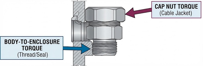
Two interfaces, two torque values
Body-to-enclosure: Entry thread plus sealing washer or O-ring. Apply the gland manufacturer's published torque data (see also IEC 62444).
Cap nut onto the cable: This sets insert compression on the jacket.
Over-torquing the cap nut can deform soft PVC or TPE jackets and cause cold flow, with a slow loss of seal over time. Use calibrated torque tools and record the applied values.
What Controls Connector Potting Quality?
Pre-potting mating force check
Potting is effectively irreversible. Before encapsulation, verify that each connector mates and unmates within its specified force range; EIA-364-13 is the common reference procedure. The check catches bent contacts, housing damage from upstream soldering or handling, and misalignment. Mask the mating faces and verify the masking before dispensing.
Material selection
| Chemistry | Strengths | Watch-outs |
|---|---|---|
| Epoxy | Rigid, chemically resistant, strong adhesion | CTE mismatch stress; brittle under thermal cycling |
| Polyurethane | Flexible, moisture and abrasion resistant | Moisture-sensitive during cure; prone to bubbling |
| Silicone | Widest temperature range, low component stress | Weaker adhesion; may need primer |
For outdoor nodes with wide daily temperature swings, lower-modulus materials generally reduce stress on solder joints and connector bodies.
Degassing, dispensing, and cure
Pre-dry the PCBA and connector bodies. This is critical for polyurethane, where absorbed moisture generates CO₂ bubbles.
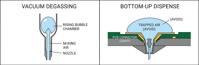
Vacuum-degas the mixed material within its pot life.
Dispense from the lowest point and fill slowly, so air is pushed upward instead of trapped under components.
Follow the supplier's cure schedule and watch exotherm in large pours. A staged cure limits peak temperature and residual stress.
Record mix ratio, material lot, and cure profile against each unit's serial ID, so field failures can be traced to their root cause.
What Are the Common Process Root Causes of Seal Failure?
| Failure | Typical root cause | Countermeasure |
|---|---|---|
| Lid leak at one corner | Sequential, single-pass tightening | Cross-pattern, multi-pass torque |
| Leak along cable | OD at edge of gland range | Incoming OD check; mid-range selection |
| Gland body leak | Missing washer; uncontrolled thread torque | Separate body torque spec |
| Potting voids | No degassing; damp substrate; top-down fill | Pre-dry, degas, bottom-up dispense |
| Late-life seal loss | Compression set; cracked epoxy | Datasheet compression window; lower-modulus potting |
How Is Seal Integrity Verified in Production?
Immersion testing per IEC 60529 is a type test: slow, pass/fail, and with no diagnostic value. For production, pressure-decay (or vacuum-decay) leak testing is the practical verification step:
Method: Pressurize the sealed enclosure to a defined pressure, stabilize, and measure the pressure drop over a fixed time.
Acceptance limit: Derive it from correlation units, meaning known-good and deliberately leaking samples validated against immersion testing.
Placement: Test after closure and gland installation, and after potting cure where potting forms part of the seal path.
Decay testing verifies process consistency. It does not replace the IP type test.
Sealing Process Self-Check
Gasket compression range confirmed against the supplier datasheet
Cross-pattern, multi-pass lid torque sequence defined in work instructions
Cable OD measured on incoming lots; glands selected for mid-range fit
Separate torque specs for gland body and cap nut, applied with calibrated tools
Connector mating force verified and mating faces masked before potting
Potting material matched to the thermal and chemical environment; substrate pre-dried
Vacuum degassing and bottom-up dispensing specified
Leak-test acceptance limit correlated to IP type-test results
FAQ
Can conformal coating replace potting for IP67?
No. Conformal coating protects the board surface from condensation, but it does not seal enclosure or connector interfaces.
Should a sealed outdoor enclosure include a vent?
Often, yes. A membrane pressure-equalization vent relieves thermal-cycling pressure on seals, but it must be included in the IP type test.
Can a potted connector be reworked?
Rarely. Silicone can sometimes be removed; rigid epoxy usually cannot be removed without board damage, so check mating force before potting.
Plan Sealing Into the PCBA Build
PCBCart assembles PCBA under an IATF 16949 quality management system, with Smart MES UID traceability. If you're preparing an outdoor industrial IoT build, send us your PCBA files together with your enclosure and sealing requirements. That way connector selection, placement, and board cleanliness are aligned with your sealing process from the first build.
Helpful Resources
Conformal Coating Application in PCB Assembly
Powerful Tips to Help PCBs and PCBAs to Better Work in Harsh Environment


