



Fine-pitch QFN and BGA components are now standard on medical monitoring device assemblies — patient monitors, pulse oximeters, infusion pump controllers, and diagnostic imaging front-ends all rely on them. Rework is, at times, unavoidable: a failed post-reflow AOI call, a socket-test escape, a field-return investigation. However, rework on a 0.4mm or 0.5mm pitch package is not a routine touch-up procedure. It constitutes a controlled thermal and mechanical event that must be bounded, inspected, and documented with the same rigor as the original assembly process — arguably more so, given the reliability expectations attached to monitoring-class medical electronics.
Engineering Risk Profile of Fine-Pitch Rework
Rework risk does not scale linearly with pitch reduction; it compounds. Three failure mechanisms warrant particular attention.
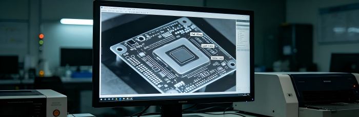
Pad Lifting and Land Damage
QFN packages rely on exposed pads and perimeter lands with limited copper mass at fine pitch. Repeated localized reflow elevates the risk of:
Pad lifting — separation of the copper land from the laminate, typically resulting from excessive dwell time at peak temperature or from mechanical stress during component removal
Land cratering — a subsurface fracture beneath the pad, undetectable by visual inspection but identifiable under X-ray or as an intermittent open during subsequent thermal cycling
Solder mask damage at the pad periphery from repeated hot-air exposure, which may expose adjacent copper features not intended for that thermal load
At 0.4mm pitch, the margin between sufficient reflow to release the joint and damage to the underlying land is narrow, and this margin narrows further with each successive rework cycle at the same site.
Thermal Damage to Adjacent Components
Fine-pitch rework typically employs localized hot-air or infrared rework stations with a nozzle profile sized to the target package. The corresponding risk is heat propagation to neighboring components:
Passive components (0201/01005 case sizes common on monitoring-device boards) positioned near the rework site may experience reflow-adjacent temperatures despite not being the intended target
Adjacent BGA or QFN packages already soldered may undergo partial reflow, resulting in shifting without full wetting — a defect mode readily overlooked unless post-rework inspection extends to neighboring sites rather than the reworked component alone
Thermally sensitive parts near the rework zone, including connectors and switches, require masking not necessary during the original SMT reflow pass, as that process follows a controlled oven profile rather than a localized thermal spike
Cumulative Fatigue from Repeated Rework Cycles
Each rework cycle imposes a thermal excursion on the surrounding laminate and copper structures, irrespective of whether the rework itself is executed correctly. The cumulative effect includes:
Progressive weakening of plated through-hole barrels and via structures in proximity to the rework site
Laminate resin degradation with each excursion above glass transition temperature, a consideration of particular relevance on thinner or higher-layer-count boards used in compact monitoring-device form factors
Reduced solder joint reliability margin even where the rework itself passes inspection, as reliability assumptions for solder joints generally presume a bounded number of thermal excursions across the board's service life rather than an open-ended rework count
This is the underlying rationale for rework count limits: the governing risk is cumulative rather than confined to any single event, regardless of how cleanly that event inspects.
Inspection Sequence Bracketing Each Rework Event
Rework should never proceed as a "remove, replace, close out" operation on Class 3 or medical-device boards. It requires pre- and post-rework inspection that treats the rework site — and its immediate neighbors — as suspect until demonstrated otherwise.
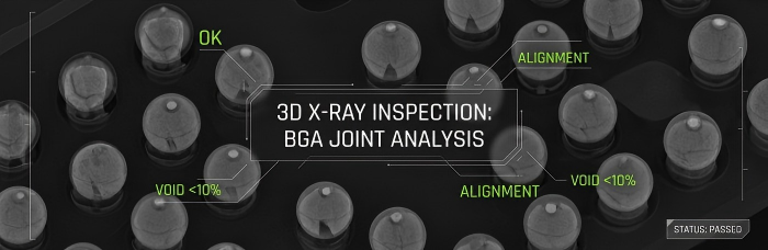
Pre-Rework Inspection
X-ray inspection of the target site prior to component removal, to characterize existing joint condition and establish a baseline against which post-rework results can be compared
3D AOI review of the surrounding component field, documenting the as-received condition of neighboring parts so that any subsequent change can be attributed correctly rather than assumed pre-existing
Post-Rework Inspection
Off-line X-ray re-inspection, evaluating voiding percentage beneath BGA/QFN thermal pads (using oblique-angle capability to assess solder ball connections not visible from a top-down view), bridging or insufficient solder at perimeter leads, and evidence of pad lift or land separation
3D AOI closed-loop inspection of the reworked component and its surrounding footprint — not the reworked component in isolation — to detect adjacent-component thermal disturbance
Electrical retest, where board-level test coverage exists, to confirm that no functional regression has been introduced that visual or X-ray inspection alone would fail to capture
Rework is considered closed only when post-rework inspection confirms both that the reworked joint satisfies acceptance criteria and that no new defect has been introduced elsewhere as a consequence of the rework thermal event.
Rework Count Limits and Documentation Requirements
IPC J-STD-001 Class 3 — the classification typically specified for high-reliability electronics, including medical devices — does not treat rework as unbounded. Class 3 assemblies are intended for products where continued performance is critical and downtime is intolerable, and this is the underlying rationale for tighter control over rework history, not merely rework technique.
The practical documentation requirements that follow from this classification include:
Per-site rework count tracking, tied to board serial number and component reference designator, rather than a single aggregate "board reworked: yes/no" flag
Rework history retained through Smart MES with UID traceability, such that a board's rework record — count, affected sites, and pre- and post-inspection findings — remains retrievable by serial number rather than reconstructed from paper travelers
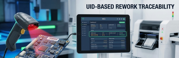
A defined maximum rework count per site, beyond which the site is dispositioned to no-rework/scrap rather than reworked indefinitely until it passes
Root cause capture for the originating defect, not merely the correction applied, since repeated rework at a given site without addressing an upstream cause — stencil aperture, paste volume, placement offset — will continue to generate rework events rather than resolve the underlying issue
Relevance of Rework Documentation to Client Quality Systems
For OEMs producing monitoring-class medical devices, rework records extend beyond an internal manufacturing artifact; they feed directly into the OEM's own design history file and device master record obligations. A record specifying serial number, affected site, defect identified, inspection method applied, and final disposition supports:
Traceability audits in which a regulatory body requests the manufacturing history of a specific unit or lot
Root cause investigations where a field return correlates with a documented rework history
Supplier quality audits in which the OEM's quality function requires evidence that rework was controlled and inspected, rather than simply performed
An EMS partner capable of producing this record on demand, tied to UID and MES data rather than reconstructed retrospectively, reduces the OEM's own audit burden — a meaningful differentiator for HMLV medical device programs, where lot sizes are small enough that per-unit history carries genuine weight.
For organizations evaluating rework capability and documentation practices as part of an EMS qualification process for a medical monitoring device program, PCBCart can walk through how rework risk is bounded and documented on Class 3 fine-pitch assemblies. Submit your board details for a rework capability review.
Ressources utiles
• Free PCB DFM Check and Checklist for PCB Assembly
• DFM Audit Checklist for Industrial PCBA: 38 Design Rules That Cut Rework Rate
• ESD Control Protocols in PCBA Assembly for Sensitive Medical Sensor Boards


