



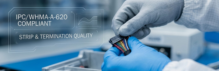
IPC/WHMA-A-620 is the consensus workmanship standard for cable and wire harness assemblies, covering stripping, termination, strain relief, and shield grounding.
In diagnostic instrument box-builds, applying it at the PCBA-to-harness interface — not just within the harness itself — is what prevents connector-level failures that look like PCBA defects but originate in the mechanical interconnect.
Diagnostic instruments rarely fail at the PCBA level alone. In box-build assemblies — analyzers, imaging subsystems, point-of-care platforms — a disproportionate share of field returns trace back to the interconnect layer: a harness termination that met visual inspection but not mechanical spec, a connector interface that passed continuity at first-article but degraded after repeated mating cycles, or a strain relief detail that was never called out on the drawing. IPC/WHMA-A-620 exists specifically to close that gap. For an EMS provider handling full box-build integration rather than bare PCBA, applying A-620 rigorously at the harness level is not optional scope — it's the difference between a board that tests good in isolation and an instrument that survives its service life.
This article walks through where A-620 acceptance criteria intersect with PCBA-to-harness integration in diagnostic instrument builds, the interface failure modes we see most often, how harness traceability folds into MES recordkeeping, and what electrical verification looks like at the connector boundary.
What IPC/WHMA-A-620 Actually Governs
IPC/WHMA-A-620, jointly maintained by IPC and the Wire Harness Manufacturers Association, is the consensus workmanship standard for cable and wire harness assemblies — conductor stripping and preparation, crimp and solder terminations, connector and contact installation, shield termination, strain relief, and bundling/lacing. It is a visual, criteria-based standard: each requirement defines a target condition, an acceptable condition, a process indicator, and a defect, which removes subjective judgment calls from harness inspection.
Three acceptance classes matter here:
Class 1 — general consumer product, functional performance emphasis, cosmetic imperfections tolerated.
Class 2 — dedicated service electronics where extended life and uninterrupted service are desirable but not critical.
Class 3 — high-performance/continuous-operation equipment, including devices where failure is unacceptable. Diagnostic and life sciences instrumentation is typically specified at Class 2 or Class 3 depending on the criticality of the function the harness supports.
Three areas of A-620 do most of the work in a diagnostic box-build:
Insulation Strip Length and Conductor Condition
Strip length must match the terminal or connector manufacturer's specification, and A-620 sets tolerances on that length as well as limits on strand damage during stripping. Nicked or scraped strands reduce effective conductor cross-section — a defect that isn't visible in a continuity check at time-zero but shows up later as localized heating or fatigue failure under vibration or repeated flexing. For diagnostic instruments with motorized stages, pumps, or moving optics, wire routed near any moving assembly gets extra scrutiny on strip quality and insulation clearance.
Termination Quality — Crimp and Solder
Crimped terminations are evaluated on crimp height, conductor visibility in the crimp barrel, and insulation support — each within the terminal manufacturer's tolerance band, not a generic number. Where solder termination is used instead of crimping, A-620 aligns with IPC J-STD-001 for wetting, fillet formation, and absence of cold-joint or dewetting defects. On a diagnostic instrument harness, the termination method is usually dictated by the connector family already specified on the electrical BOM — our process engineering reviews termination method against the connector's crimp/solder pull data during DFM rather than defaulting to one method.
Strain Relief
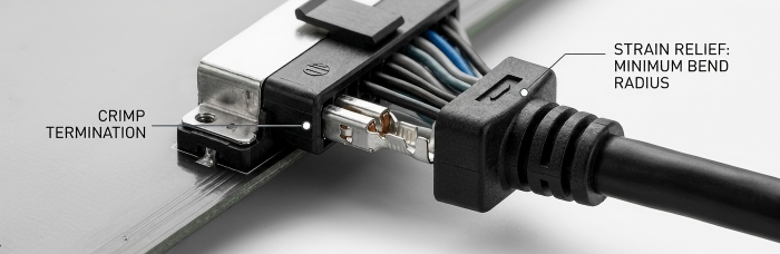
This is the single most common point of failure we see at the PCBA-to-harness interface. A-620 requires strain relief that manages tension at the cable-to-connector junction so that mechanical load on the cable is not transferred into the termination or the PCB connector footprint. The general rule of thumb applied across the standard is a minimum bend radius of roughly three times the cable's outer diameter for fixed routing (larger for cable that flexes in service, such as a harness routed through a hinge or drawer mechanism in an instrument chassis). Where a harness lands directly on a board-mount connector with no separate strain relief clip or grommet, repeated handling during service or shipping transmits pull force straight into the solder joints or press-fit pins on the PCBA — a failure mode that looks like an intermittent PCBA fault but is actually a harness design gap.
Where PCBA-to-Harness Integration Breaks Down
In box-build integration for diagnostic instruments, the interface between the board and the harness is where design intent and manufacturing reality most often diverge. Recurring issues include:
Connector footprint vs. mating connector tolerance mismatch. The PCBA connector may be within spec on its own, but keying, pin pitch, or shroud dimensions from a different supplier lot introduce mating force outside the expected range.
Unspecified strain relief at board-mount connectors. Electrical schematics define signal routing; they rarely define mechanical strain management. Without an explicit callout, harness fabrication defaults to whatever the operator judges reasonable — which is precisely what A-620 is meant to eliminate.
Shield/ground termination inconsistency. Diagnostic boards carrying sensitive analog front ends (photodiode arrays, thermocouple inputs) are sensitive to how and where a cable shield is terminated to chassis or board ground. A harness built to A-620 workmanship standards can still introduce noise if the shield termination point wasn't specified as part of the electrical design, not just the mechanical build.
Bundling and routing near thermal or EMI sources. Harnesses routed near the reflow-processed board assembly or power conversion sections need clearance and, where applicable, sleeving called out at the box-build integration stage — not left to be resolved during final assembly.
We treat harness-to-PCBA interface definition as its own DFM checkpoint, separate from PCBA DFM, precisely because these issues surface at the mechanical integration stage rather than at bare-board or SMT process review.
Folding Harness Traceability into MES Records
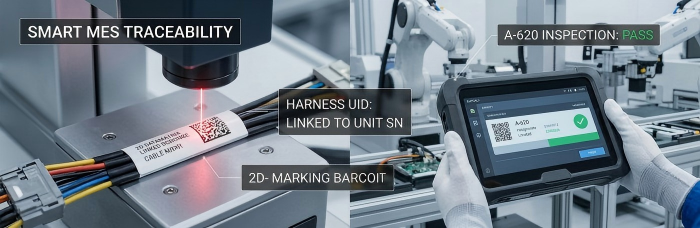
For diagnostic and life sciences instrumentation, harness assemblies need the same level of record integrity as the PCBA they connect to. Our Smart MES platform, which assigns UID-based traceability at the board level with laser marking, extends that same lot- and operator-level record to harness sub-assemblies feeding into the box-build: wire and connector lot numbers, crimp tool calibration status at time of termination, operator certification reference, and inspection disposition (accept, process indicator, or defect per A-620 criteria) are captured against the harness UID and linked to the final unit serial number at integration. This means a field issue traced to a specific harness batch can be cross-referenced against the exact PCBA units it was paired with, rather than requiring a full-lot investigation.
Electrical Interface Verification at the PCBA Boundary
Workmanship compliance under A-620 confirms the harness was built correctly; it doesn't confirm the harness-to-PCBA interface performs correctly under the connector's actual service conditions. Two checks close that gap:
Connector mating/unmating force verification — confirming insertion and extraction force falls within the connector manufacturer's specified range, particularly important for connectors that will be mated and unmated repeatedly during instrument service or calibration.
Continuity and isolation testing at the harness-to-PCBA junction — verifying every net through the harness against the PCBA's connector pinout, including shield continuity where specified, before the harness is accepted into box-build integration rather than deferring discovery to final functional test.
Running these checks at the sub-assembly stage, rather than only at final instrument test, keeps a harness-level defect from consuming downstream PCBA and integration labor before it's caught.
Harness and cable assembly quality is easy to under-scope in a box-build quote because it sits between electrical design and mechanical integration, with no single discipline fully owning it. If your diagnostic instrument program has PCBA-to-harness interfaces that haven't been reviewed against A-620 acceptance criteria, that's a gap worth closing before it reaches final test — not after.
PCBCart's engineering team reviews electrical schematics, connector BOMs, and harness drawings together as part of box-build DFM, not as separate quotes. Submit your project details for a box-build assessment and receive engineering feedback on harness-to-PCBA interface risk alongside your quote.
Helpful Resources
● Managing Thermal Reliability in Diagnostic Instrument PCBA
● IATF 16949 PCBA Assembly: Zero-Defect Protocols for Automotive Electronics
● What is Turnkey Box Build Assembly in EMS?


