



Test strategy selection for PCBA is a coverage-versus-cost decision, not a fixed hierarchy of methods. For low-to-mid volume production — typical in industrial automation, life sciences, and semiconductor test equipment programs — the deciding factor is rarely theoretical coverage alone; it is whether fixture investment is justified by the volume a board will actually see. This article compares ICT, Flying Probe, and Functional Test on coverage, fixture cost, and test time, and covers combined strategies for HMLV (High-Mix, Low-Volume) production.
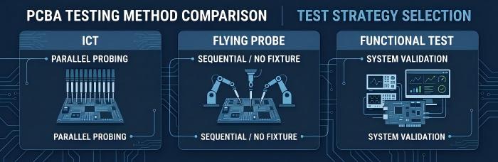
Quick Comparison: ICT vs Flying Probe vs Functional Test
| ICT | Flying Probe | Functional Test | |
|---|---|---|---|
| Coverage | High — component values, polarity, shorts/opens | Comparable to ICT; limited on buried BGA/QFN nets | System-level function — firmware, timing, interaction |
| Fixture cost | Highest — custom bed-of-nails per revision | Low to none — CAD/Gerber-driven programming | Variable — simple harness to custom jig |
| Per-unit test time | Fastest — parallel probing | Slower — sequential probing | Typically longest — power-up/functional sequences |
| Best fit | Stable design, high or growing volume | HMLV, frequent revisions, limited test access | Any volume where function can't be inferred from components alone |
Why Volume Changes the Calculus
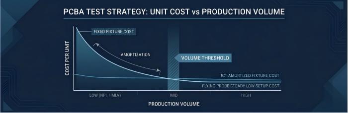
At high volume, ICT's upfront fixture cost amortizes quickly, making it the practical default. At low-to-mid volume — hundreds to low thousands of units per build, with frequent revisions — a bed-of-nails fixture built for a board that changes six months later becomes a sunk cost. Test strategy in HMLV is therefore a per-board decision, not a fixed policy.
Coverage, Fixture Cost, and Per-Unit Test Time
In-Circuit Test (ICT)
ICT uses a bed-of-nails fixture with probes contacting dedicated test points to verify component values, polarity, shorts, opens, and basic parametrics.
Coverage: High for component-level defects when test point access is adequate.
Fixture cost: Highest of the three — a custom fixture per board revision, plus test points reserved in the layout during DFM review.
Test time: Fastest once built — all nets are contacted in parallel.
Constraint: Requires dedicated test point real estate at the design stage; space-constrained boards may not be ICT-testable without a redesign.
Flying Probe Test
Flying Probe Test uses moving probes, guided by CAD-derived programs, contacting test nodes sequentially rather than through a physical fixture.
Coverage: Comparable to ICT for component- and net-level defects, with some limitation on high-pin-count BGA/QFN nets not accessible from the board surface — a gap upstream AOI and X-ray inspection help close.
Fixture cost: Low to none — programming is software-driven from CAD/Gerber data.
Test time: Slower than ICT, since probing is sequential; scales with net count and complexity.
HMLV advantage: Program changes are a software update, not a hardware rebuild, when revisions are frequent.
Functional Test (FCT)
Functional Test exercises the assembled board under power to verify it performs as a system, not just that individual components are within spec.
Coverage: Validates system-level behavior — power sequencing, timing, communication interfaces, sensor response — that component-level test cannot. A board can pass ICT or Flying Probe with every component correct and still fail functionally due to firmware or interaction faults.
Fixture cost: Variable — from simple power-and-measure harnesses to custom jigs with embedded software, often built to the customer's own functional specification.
Test time: Typically the longest of the three, given power-up sequencing and multi-stage checks.
Fixture Payback at Low-to-Mid Volume
The question for ICT at this volume tier is simple: does the fixture cost, amortized across expected volume, still beat the per-unit cost of the alternative? As an illustrative example, not project data: a fixed fixture cost spread across 200 units dominates per-unit cost; spread across 20,000, it's negligible. This is why ICT remains standard at high volume but is often bypassed for HMLV boards, where volumes are lower, revisions are frequent, and test point space competes with component density. Flying Probe's near-zero fixture cost removes this calculation, at the cost of longer test time — an acceptable trade when volume is too modest for ICT to pay back anyway.
Not sure which side of the payback line your board falls on? Get a fixture-cost and test-time estimate for your specific design.
Where Functional Test Adds Value
ICT and Flying Probe confirm a board was built correctly against its BOM and netlist — not that it performs its intended function once powered. A bus that fails to initialize, an out-of-range sensor input, or a sequencing error can pass every component-level test and still fail in application. Functional Test matters most where boards depend on:
Firmware tied to hardware timing
Multiple, sequenced power rails
Analog front-ends sensitive to tolerance stack-up
Communication interfaces requiring end-to-end validation
Combined Strategy: Flying Probe + Functional Test for HMLV
For most low-to-mid volume programs, Flying Probe for component- and net-level screening, paired with Functional Test for system-level validation, offers the strongest coverage-to-cost ratio. Flying Probe catches solder and placement defects without fixture investment and adapts to revisions in software; Functional Test catches behavioral faults Flying Probe structurally cannot, typically with a simpler, more reusable fixture. Upstream 3D AOI and offline X-ray inspection — including oblique-angle imaging for BGA/QFN voiding — further reduce the defect burden electrical test carries. ICT re-enters once volume stabilizes and revisions slow, typically past the NPI phase.
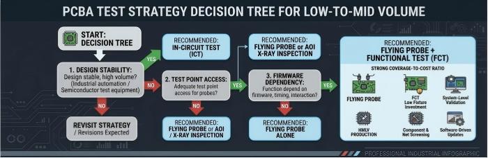
Test Strategy Decision Tree
Design stable, with high or growing volume? Yes → ICT is likely justified; proceed with test point DFM review. No → step 2.
Adequate test point access for probe-based testing? No → Flying Probe or AOI/X-ray-led inspection is the practical path. Yes → step 3.
Does function depend on firmware, timing, or interaction component-level test can't verify? Yes → add Functional Test to Flying Probe. No → Flying Probe alone may suffice.
Still in NPI or early production, with revisions expected? Yes → favor Flying Probe + Functional Test until design and volume stabilize.
Revisit strategy at each major revision and volume milestone — a plan fixed at NPI is rarely still correct once a program matures.
Ready to scope a test strategy for your next build? Submit your project for a test plan review and get a coverage and fixture-cost recommendation matched to your volume and timeline.
FAQ
Is ICT always more accurate than Flying Probe? Not necessarily. Both offer comparable component- and net-level coverage when access is adequate. ICT is faster per unit once built; Flying Probe is slower but needs no fixture, favoring boards with limited test access or frequent revisions.
When does ICT fixture investment make sense for HMLV production? Once the design has stabilized and volume is high enough that the amortized fixture cost undercuts Flying Probe or Functional Test per unit. Programs still in NPI, or with frequent revisions, rarely reach that payback point.
Can Functional Test replace ICT or Flying Probe? No. It validates system-level behavior but doesn't systematically verify component values, polarity, or solder joint integrity — it complements component-level test rather than replacing it.
Does Flying Probe test every net on a board? Coverage depends on probe access. Nets buried under fine-pitch BGA/QFN packages may have limited surface access — why upstream AOI and X-ray inspection cover the placement and solder-joint defects probing can't reach.
Helpful Resources
• Comparison of AOI, ICT and AXI and When to Use Them during PCB SMT Assembly
• Printed Circuit Board Assembly Inspection Methods
• Designing for Testability (DFT) in PCB Assembly
• 10 Questions to Ask Any EMS Partner Before Signing
• Automated X-Ray Inspection (AXI) for PCB Assembly Quality


