



Industrial IoT boards (gateways, sensor nodes, edge controllers) are rarely finished when the last component is soldered. The board only becomes a product once firmware is loaded, and that step is often the weakest link in the traceability chain. This article covers how MES-based tracking can make firmware programming a recorded, auditable process step rather than an informal one.
Why Firmware Version Control Fails on the Line
In low-volume, high-mix assembly, the same board design may be built several times a year. Each build can carry a different firmware release, and a single order may be split across calibration or configuration variants. Common failure modes include:
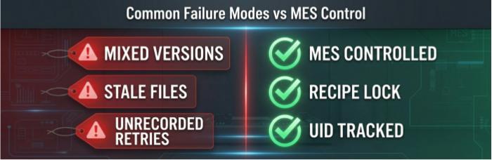
Mixed firmware versions in one lot. An engineering change moves from v1.4 to v1.5 mid-order, and boards programmed before and after the change are not segregated.
Stale image files. An operator loads a programming file from a local folder that was never updated.
Unrecorded retries. A board fails programming twice, passes on the third attempt, and nothing in the record shows it.
No link between a physical board and a firmware release. Weeks later, no one can say which image a field unit received.
The consequence appears in the field. Two boards that look identical behave differently: one reports sensor data at a different interval, another handles a communication timeout differently, and a firmware-related fault is hard to separate from a hardware fault. Without a per-board record, the investigation becomes a lot-wide suspicion exercise.
Binding Firmware Version to Board Serial Number in MES
The foundation is a unique identifier on each board. In a Smart MES with UID traceability and laser marking, each PCBA receives a laser-marked UID, which becomes the key that every later record attaches to. For firmware, the MES record should tie together:
Board UID/SN (the primary key)
Firmware image identifier (file name, version string, and ideally a checksum of the released image)
Programming timestamp
Programming station ID
Result: pass, fail, and retry count
Operator or process-recipe identifier
The most useful design choice is recipe control. Instead of an operator selecting a file, the work order carries the approved firmware release as a controlled parameter. The station loads what the work order specifies, and the MES records what was actually loaded. When the two differ, the board is flagged rather than passed silently. Whether this is enforced as a hard interlock or a recorded exception is a project-level decision.
A checksum matters more than a version label. A version string is typed by a person, while a checksum is computed from the file, so it can confirm that the image on the line matches the image the customer released.
Recording Retries and Failures, Not Just Passes
A pass/fail flag alone hides process information. Recording retry counts separates three situations that look the same in a yield report:
First-pass success: normal.
Pass after retry: possibly a marginal connection, contact issue, or power-rail problem worth reviewing.
Fail after allowed retries: board is held for diagnosis, not reworked blindly.
A board that needs several attempts to program is a signal. It can point to a contact problem at the programming interface, a solder joint issue near the programming pins, or a supply problem on the board. Capturing it gives engineering something to analyze before the board reaches a customer.
Linking Programming Data to Functional Test (FCT)
Programming and functional test should read from the same board record. When the FCT station scans the UID, the MES can confirm that:
The board has a successful programming record, and
The recorded firmware version matches the work-order requirement.
If either check fails, the board does not proceed. This prevents a common gap in which an unprogrammed or wrongly programmed board is tested against the wrong expectations, or skips a step entirely.
Batch Isolation When Programming Failure Rates Drift
Programming data also works as a process monitor. A framework for responding to abnormal failure rates:
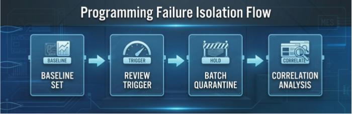
Define a baseline for the product from early builds, with the customer.
Set a review trigger, such as a rise in first-attempt failures or retries over a defined window.
Hold affected material. Using UIDs and station timestamps, identify which boards passed through the affected station, time window, or component lot, and quarantine those rather than the whole order.
Investigate by correlation. Compare failing boards against the station, fixture, reflow or solder-process records, and component lot data.
Illustrative example (hypothetical): suppose retry counts rise for boards programmed on one station after a fixture change. Because each record carries a station ID and timestamp, the affected boards can be isolated and the fixture examined, without holding boards programmed elsewhere. The numbers are not the point; the ability to scope the hold is.
Where upstream process records are linked, such as 3D SPI and 3D AOI results or X-Ray inspection of BGA/QFN voiding, a programming failure cluster can be cross-checked against those data to separate a solder-related cause from a firmware or tooling cause. This depends on those records being tied to the same UID within the project's MES configuration.
How Customers Can Use These Records for Field Firmware Audits
Traceability pays off after shipment. With a per-UID record, a customer can:
Verify a field unit's firmware lineage. Given a serial number, look up which image and version were loaded at the factory and when.
Scope a firmware-related issue. If a defect is found in a specific release, identify which serial numbers shipped with it and which did not, instead of recalling or re-flashing an entire population.
Reconcile against deployed-device data. Compare factory-recorded versions with versions reported by devices in service. A mismatch indicates either a field update or a factory-side discrepancy worth investigating.
Support internal and regulatory documentation. Industrial and connected-product customers increasingly need to show control over software and firmware provenance. Frameworks such as IPC-1782 (traceability for electronic products) give a reference structure for what manufacturing records should capture.
A caveat on interpretation: these are manufacturing records generated by process controls. They document what was loaded and when. They are not a substitute for the customer's own firmware release management or security validation.
Suggested Firmware Programming Traceability Fields
Use this list as a starting point when defining requirements for a project.
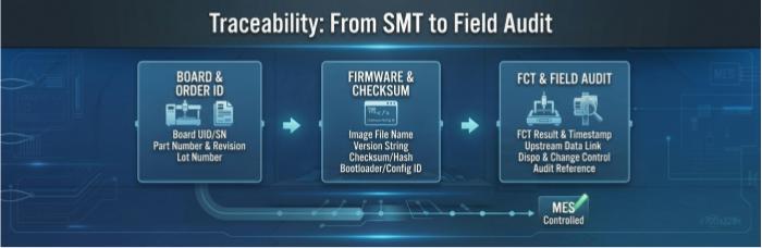
Board and order identification: board UID/serial number, PCBA part number and revision, work order or lot number.
Firmware and programming event: firmware image file name, version string, image checksum or hash, bootloader version and configuration/parameter file identifier (if separately loaded), programming date and time, station ID and fixture ID, programming tool or interface identifier, result (pass/fail), attempt count, and failure code or message (if captured).
Linkage and change control: version-match check result (loaded vs. work-order requirement), functional test result and timestamp, link to upstream inspection records (SPI/AOI, X-Ray) where applicable, disposition for held or reworked boards, customer-approved image release reference, and change-control reference when the firmware version changes mid-order.
Next Step: Request a Traceability Requirements Assessment
If your IoT boards are programmed during assembly, the practical question is which of these fields your own quality system and field-support process actually need. Submit your project (BOM, assembly files, firmware release process and any audit requirements) to PCBCart for a traceability requirements assessment. Our engineering team will review how programming, test and MES records can be configured around your product, and confirm what can be supported before the build begins.
Helpful Resources
• MES-Driven Lifecycle Tracking for ATE Interface Boards: Probe-Cycle and Rework History
• Traceability from Silicon to System: MES Implementation in Life Sciences Manufacturing
• Conformal Coating Strategies for Industrial IoT Gateway Boards in Harsh Environments
• X-Ray BGA Void Inspection for Industrial Power Modules


