



Pin-in-paste lets a few through-hole parts solder in the same reflow pass as the surface-mount parts. On mixed-technology boards that carry only a handful of connectors or headers, that removes a second soldering operation, a second thermal cycle on the SMT joints, and the setup that goes with it. It works only when three things line up: the part survives the full reflow profile, the stencil can deliver enough paste to fill the barrel, and the hole and lead geometry don’t waste that paste.
This article covers how we decide whether a board is a pin-in-paste candidate, how the paste volume is sized, and what to put in your RFQ so the decision is made before the stencil is cut rather than after the first article.
What is pin-in-paste, and how is it different from wave or selective soldering?
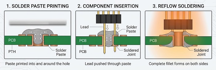
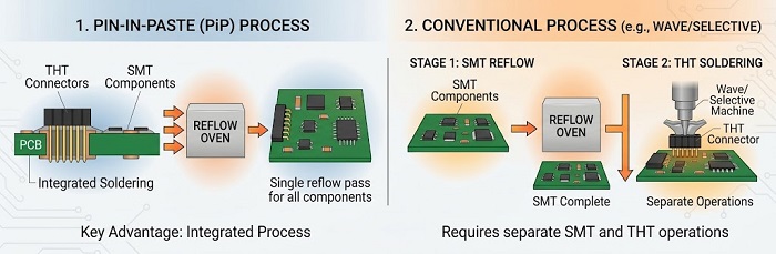
Pin-in-paste (also called intrusive reflow, through-hole reflow or paste-in-hole) prints solder paste into and around a plated through-hole, inserts the component lead through that paste, and solders the joint in the reflow oven together with the SMT parts. As the paste melts, the solder wicks down the barrel and forms the joint on both sides of the board.
The conventional alternative is wave or selective soldering after reflow: the board finishes SMT, the through-hole parts are inserted, and the leads are soldered in a separate operation. Pin-in-paste folds that second operation into the first. The trade-off is that everything the through-hole joint needs has to come from the stencil, and the through-hole part has to ride through the oven.
When does pin-in-paste make sense on a high-mix board?
It makes sense when a board has a small number of reflow-rated through-hole parts and the geometry lets the stencil supply enough solder. In high-mix, low-volume work that matters more than it does on a long production run, because every separate soldering operation carries its own per-job setup: a selective soldering program and nozzle choice, or a hand-soldering work instruction and operator time. Removing that step shortens the build and removes one source of variation.
It makes less sense when the through-hole count is high, when the parts can’t take reflow temperatures, or when the acceptance class demands a fill the paste volume can’t reliably reach. The comparison below is how we frame the choice in DFM review.
| Pin-in-paste | Selective soldering | Hand soldering | |
|---|---|---|---|
| Extra step after reflow | None | Yes, programmed nozzle | Yes, operator |
| Thermal cycles on SMT joints | One reflow | Reflow plus localized solder wave | Reflow plus local iron heat |
| Setup per new job | Stencil apertures | Program, nozzle selection, sometimes a fixture | Work instruction |
| Component limit | Body must survive the full reflow peak | Body stays out of oven-level heat | Most parts |
| Main risk | Insufficient barrel fill | Nozzle access in tight layouts | Joint-to-joint variation |
| Typical fit | A few reflow-rated THT parts | Many THT joints or heat-sensitive parts | Very few joints or awkward geometry |
Which components can’t go through pin-in-paste?
The deciding factor is whether the component body is rated for your reflow profile. A through-hole part soldered by wave or selective soldering keeps its body above the board, away from most of the heat. In pin-in-paste, the whole part goes through the oven at the same peak temperature as the SMT parts. Check the datasheet for a reflow or maximum soldering temperature rating before you list a part for pin-in-paste.
Parts that often fail that check include plastic connector housings that aren’t specified for reflow, aluminum electrolytic capacitors, relays, and some switches, transformers and potentiometers. Many connector families are offered in reflow-rated versions, so the fix is often a part number change rather than a process change.
Two mechanical points matter as well. The part needs some standoff, so the overprinted paste around the hole isn’t trapped under a flush-seated body. And pins tied directly into large copper planes may not reach wetting temperature in a profile set for the rest of the board; thermal relief on those connections helps, and it’s something we flag during review.
How much solder paste does a pin-in-paste joint need?
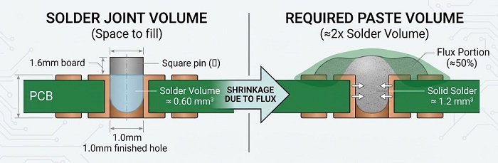
About twice the volume of solder you want in the joint, because roughly half of solder paste by volume is flux that doesn’t remain after reflow. The solder you need is the space between the barrel wall and the lead, plus the top and bottom fillets. That is the number the stencil has to deliver, and it’s usually larger than people expect.
A worked example
Here is the arithmetic for one pin of a 2.54 mm-pitch header, using illustrative dimensions: a 1.6 mm board, a 1.0 mm finished hole and a 0.64 mm square pin.
• Barrel volume: π × (0.5 mm)² × 1.6 mm ≈ 1.26 mm³
• Pin volume inside the barrel: 0.64 mm × 0.64 mm × 1.6 mm ≈ 0.66 mm³
• Space to fill with solder: ≈ 0.60 mm³
• Paste needed for that solder: ≈ 1.2 mm³, before the fillets
With a 0.12 mm stencil, 1.2 mm³ of paste needs roughly 10 mm² of aperture per pin, about 3.2 mm × 3.2 mm. On a 2.54 mm pitch that would merge with the neighboring apertures. So the deposit has to be reshaped (elongated across the row rather than along it), thickened locally with a step-up stencil, or the hole and lead combination has to change. A locally thicker area reduces the aperture area needed in proportion to the added thickness, but the step needs keep-out distance from fine-pitch parts nearby.
These figures ignore the paste pushed into the barrel during printing and the stencil’s transfer efficiency, both of which shift the result. Treat them as a sizing starting point; the first article confirms the fill.
What hole and lead geometry makes pin-in-paste work?
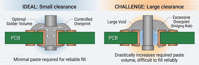
Geometry decides how much of the paste goes into a useful joint. Three dimensions carry most of the weight.
Hole-to-lead clearance. Every extra fraction of a millimeter in hole diameter adds volume that has to be filled. In the example above, opening the hole from 1.0 mm to 1.1 mm raises the space to fill to about 0.87 mm³, roughly 44% more paste for the same pin. Keep the finished hole as tight as the lead and the insertion method allow.
Board thickness. Barrel volume scales directly with thickness. The same hole and pin on a 2.4 mm board need about 50% more solder than on a 1.6 mm board, which is often what pushes a thick industrial board toward selective soldering.
Lead length and protrusion. A lead that protrudes far below the board pushes paste out of the barrel as it is inserted, and that paste ends up as a blob on the lead tip instead of in the joint. Leads trimmed to a short protrusion keep more of the paste where it belongs.
Overprinting paste beyond the pad onto the solder mask is normal for pin-in-paste, since the paste pulls back toward the pad as it melts. It does need clearance from neighboring SMT pads and vias, or the overprint becomes a bridging or solder-ball risk.
How do we verify barrel fill on pin-in-paste joints?
The visible fillets on top and bottom don’t show what happened inside the barrel. Optical inspection checks the fillets; X-ray inspection shows how far the solder actually climbed. For a new pin-in-paste design, the first article is where that fill is confirmed against the agreed criteria before the rest of the run continues.
IPC-A-610 generally sets a minimum of 75% vertical solder fill for plated through-holes in Class 2 and Class 3 assemblies, with a narrower exception for some Class 2 holes. Those criteria change between revisions, so name the revision your contract follows. If a Class 3 board can’t close the paste-volume calculation with margin, we’d rather move those parts to selective soldering at the quote stage than discover it on the first article.
What should you put in your RFQ for a pin-in-paste build?
Pin-in-paste is a stencil decision, so the information has to arrive before the stencil is designed. Include the following with your files, or in the note field of the assembly quote form:
• Reference designators of the parts you want soldered by pin-in-paste, and any through-hole parts that must not be.
• Reflow rating for each of those parts, or the manufacturer part numbers so we can check the datasheets.
• Finished hole size and lead dimensions, or the connector part number and the footprint used.
• Board thickness and whether the pins connect to planes directly or through thermal relief.
• Acceptance class (IPC-A-610 Class 2 or Class 3, with revision) and any fill requirement beyond it.
• Whether a step-up stencil is acceptable, since it adds stencil cost and lead time.
• Your fallback rule: if the fill target can’t be met, may we move a part to selective or hand soldering, and does that need your approval first?
Our free DFM check runs your design through Valor DFM/DFA analysis, which covers drill sizes, pad and solder mask relationships, and paste coverage on SMD pads. For pin-in-paste candidates, we add the paste-volume and part-rating review described above, and come back to you with any part we don’t think should go through the oven.
FAQs
Can pin-in-paste be used on both sides of a double-sided board?
Usually it is applied on the side reflowed last. A pin-in-paste part on the side reflowed first would go through the second reflow upside down, and heavier through-hole parts may not stay seated. We review side assignment for these parts in DFM.
Does pin-in-paste change the reflow profile?
It can. The profile has to bring the barrel and any high-mass pins to wetting temperature without exceeding the limits of the SMT parts or the through-hole bodies. A thermocouple placed at a pin-in-paste pin is a common way to confirm that on the first build.
Will pin-in-paste joints look different from wave-soldered joints?
Often, yes. Fillet shape on the insertion side can differ, and flux residue around the pin is typical with no-clean paste. That isn’t a defect in itself, but it’s worth agreeing on visual acceptance criteria in the assembly drawing so inspection judges the joints against the right reference.
Can an existing design move from selective soldering to pin-in-paste without a layout change?
Sometimes. If the parts are reflow-rated and the hole, lead and pitch allow enough paste, the change can be limited to the stencil. If the hole is oversized for the lead or the pitch leaves no room for the deposit, the footprint has to change, and the selective soldering route may stay the better choice until the next revision.
What if the board is conformally coated?
Tell us at the RFQ stage. Flux residue around pin-in-paste joints becomes part of the cleaning and coating plan, and some coating specifications call for cleaning before application.
Get a Pin-in-Paste Assembly Quote
Helpful Resources
• Free DFM Check
• How to Quote and Order PCB Assembly Services
• Selective Soldering for Mixed-Technology Motor Drive Boards: Eliminating Thermal Damage on Adjacent SMD


