



Camera and image sensor modules occupy a unique space in electronics assembly. Unlike a typical digital PCBA, their performance is judged not just by electrical continuity but by image quality — sharpness, color fidelity, and signal cleanliness. That shifts the assembly conversation toward mechanical precision and electromagnetic discipline as much as solder joint integrity. For engineers designing industrial inspection cameras, machine vision modules, or videoscope camera heads, understanding how assembly decisions affect optical and electrical performance is essential when selecting or briefing a contract manufacturer.
Why Optical Alignment Precision Matters
An image sensor module is fundamentally an optomechanical assembly. The sensor die, its cover glass, the lens holder or barrel, and the mounting PCB all have to sit on a common optical axis, or image quality degrades in ways that are hard to correct downstream.
Tilt between the sensor plane and the lens introduces uneven focus across the frame — sharp in one corner, soft in another — an effect often called field curvature or focus shading, and it's difficult to compensate for in software. Lateral offset between the sensor's optical center and the lens axis shifts the effective field of view and can introduce vignetting at the frame edges. Even small variations in the standoff height between the sensor and lens mount change back focal distance, which affects both focus and magnification.
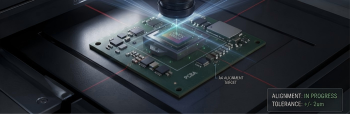
Because these effects compound across a small number of parts, alignment tolerances in camera module assembly are typically much tighter than what's common in general digital PCBA. This has practical implications for how a module is designed and built:
Fixture design matters as much as the BOM. Sensor placement and lens mounting often benefit from dedicated fixturing rather than relying on connector or housing tolerances alone.
Process repeatability matters more than peak accuracy. A process that reliably lands within a moderate tolerance window, run after run, is often more valuable than one capable of tighter results with higher variance.
Inspection needs to catch optical defects, not just electrical ones. Standard continuity and placement checks won't necessarily reveal a tilted sensor or a lens seated slightly off-axis — that typically requires functional imaging tests as part of the assembly or test process.
Engineers designing camera modules should treat alignment as a first-class requirement in the assembly spec, not an assumption that "the parts will just fit together."
Noise and Interference Considerations in Sensor Module Assembly
Image sensors output very small analog or low-voltage differential signals before any onboard amplification or digitization, which makes them sensitive to the same layout and assembly factors that affect any high-speed, low-noise circuit — but with the added consequence that noise shows up visibly, as banding, graininess, or color artifacts in the captured image, rather than as an abstract signal-integrity spec.
A few general considerations that engineers commonly weigh when specifying camera module assembly:
Grounding and shielding continuity. Camera modules frequently rely on shield cans, grounded lens barrels, or EMI gaskets to isolate the sensor from switching noise generated elsewhere in the system (motor drivers, switching regulators, wireless radios). Assembly needs to preserve these ground paths, not just place the shielding hardware.
Power supply cleanliness. Sensors are often sensitive to ripple and noise on their analog supply rails. Decoupling and filtering component placement close to the sensor, and clean routing between the power source and the sensor's supply pins, matters more here than on typical digital rails.
Signal routing for high-speed interfaces. Many sensors use MIPI CSI-2, LVDS, or similar high-speed serial interfaces to the host processor. Trace length matching and controlled impedance on these lines are design-stage decisions, but assembly needs to respect them — connector seating, cable routing, and flex circuit handling can all affect signal integrity if not controlled.

Thermal behavior. Sensor dark current and read noise increase with temperature, so modules used in enclosed housings or near other heat-generating components may need attention to thermal pathways during assembly, not just at the board design stage.
None of these are exotic requirements, but they're easy to overlook if a module is treated as "just another small PCBA" rather than an optical instrument with electronic support circuitry.
Typical Use Cases: Industrial Inspection Cameras, Videoscopes, Machine Vision
Industrial and commercial applications for camera and image sensor modules span a wide range of form factors and performance priorities:
Industrial inspection cameras used in automated optical inspection (AOI) lines, quality control stations, and defect-detection systems, where consistent focus and color accuracy across units matter for repeatable measurement.
Videoscopes and borescopes for industrial inspection of pipes, machinery interiors, and hard-to-access equipment, where compact module size and reliable performance under repeated handling are priorities.
Machine vision modules integrated into robotics, automated guided vehicles, and production-line sensing systems, where the camera module is one input into a larger control or inspection pipeline and needs to perform consistently across a production volume of units.
Across these applications, the common thread is that image quality is a functional requirement, not a cosmetic one — a misaligned or noisy module can mean missed defects, failed measurements, or degraded machine vision accuracy downstream.
If your camera or image sensor module involves chip-on-board or die-level assembly, precision component placement, or tight optomechanical tolerances, PCBCart's experience with high-mix, low-volume electronics assembly may be a good fit for your project. Get in touch with our team to discuss your camera or sensor module assembly requirements.
Helpful Resources
● IPC-A-610 Class 3 Visual Inspection Guide for Industrial & Medical Assemblies
● Solder Wicking on Wire Leads: Causes & Prevention in PCBA
● IPC/WHMA-A-620 Harness Integration for Diagnostic Instrument Box-Builds
● Box Build Assembly Services: Process, Components, and Key Requirements


