



The HMLV Sourcing Problem in Renewable Energy and Power Electronics
Sourcing PCBA for stationary renewable energy and power electronics hardware — PV inverters, grid-tied energy storage power conversion systems (PCS), industrial power distribution equipment — carries different risk than sourcing signal-level control boards. Most contract manufacturers can quote the job. Fewer can build it without a first-article failure that surfaces as a thermal, dielectric, or environmental defect once the board is under real current, voltage, and outdoor exposure.
Three friction points recur before an OEM gets past pilot production:
• Inconsistent high-voltage safety capability. Many assembly partners can quote a board with wide creepage and clearance spacing on paper but have never actually reviewed a layout against an isolation barrier requirement, or built one at volume.
• Limited real heavy copper experience. A supplier's capability page listing "heavy copper" is not the same as a production line that has solved the reflow, solder mask, and stencil printing problems that 2oz-and-up copper actually creates.
• Capacity elasticity during volume ramp. Power electronics programs often move from a handful of pilot units to a few hundred units a month within two or three quarters. A supplier sized only for prototype runs, or only for six-figure consumer-electronics volumes, tends to struggle at exactly that mid-range.
The five capability areas below give a short evaluation pass for these programs — each links to a deeper technical review for the details worth checking before tooling — followed by two questions that separate a genuine power electronics assembly partner from one quoting the work opportunistically.
Five Technical Capabilities to Verify Before Signing
1. Heavy Copper and Stepped-Stencil Capability
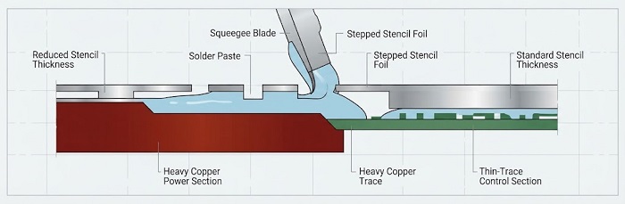
Heavy copper power planes (2oz and above) carry higher current and manage thermal dissipation without added cooling hardware, but a single panel often mixes heavy copper power sections with thin-trace control circuitry — one printing step depositing paste across two very different surface elevations. A capable partner defaults to stepped or 3D-machined stencils for that profile rather than a flat stencil that trades off print quality on one section or the other. Ask what a supplier's default stencil approach is for a mixed heavy-copper/thin-trace panel — a flat-stencil default signals heavy copper is quoted more often than it is produced.
2. High-Voltage Creepage, Clearance, and Isolation Design Review
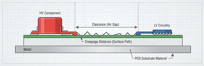
Isolation spacing between high-voltage and low-voltage sections is governed by IEC 60664-1 and IPC-2221, and depends on working voltage, transient overvoltage category, pollution degree, and material CTI — not a single blanket number. A partner's DFM review should distinguish creepage from clearance and check zone transitions, isolation component placement, and solder mask/silkscreen treatment against these variables rather than eyeballing spacing. This is a manufacturing-record check, not a safety-lab accreditation — a partner claiming EMC or calibration-lab certification should be asked to name the accrediting body. For the full five-category review — creepage/clearance, isolation component placement, mask and silkscreen treatment, test point spacing, and thermal/insulation material selection — see DFM Checklist for High-Voltage Power Electronics PCBA.
3. X-Ray Inspection for BGA/QFN Voiding Under Power Packages
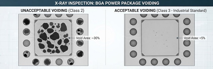
Power modules and high-current components rely on thermal vias under the package body to move heat into inner-layer copper; solder voiding under these packages reduces thermal transfer in a way that a low-current consumer board would never surface. IPC-7095D is the standard reference for BGA/QFN void acceptance — Class 2 allows up to 25% void area per solder ball, while Class 3 tightens that to under 10% and is the level continuous-duty industrial power modules generally warrant. Ask whether a prospective partner defaults to Class 3 for power packages and can produce actual void-rate inspection data rather than a general "passed AOI" statement. See X-Ray BGA Void Inspection for Industrial Power Modules for void-formation root causes and inspection parameters.
4. Nitrogen-Shielded Selective Soldering for High-Current Joints
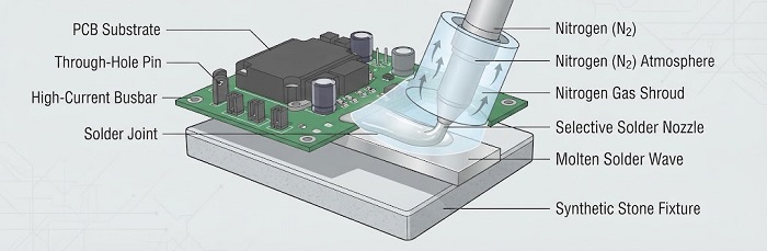
Power electronics assemblies frequently mix SMT power stages with through-hole busbars, high-current connectors, and press-fit terminals soldered via selective wave rather than reflow. Nitrogen-shielded equipment such as ZSWHPS-11-2-class selective wave soldering reduces dross formation and oxidation defects at these joints — a marginal joint here is a marginal current path, not just a marginal connection. Ask whether nitrogen shielding is standard equipment on the line or an optional add-on quoted per job, and whether synthetic stone fixtures are used for warpage-sensitive boards. See Selective Soldering ROI Reference for a cost framework comparing manual, selective, and full wave soldering for mixed-technology THT.
5. Environmental Protection for Outdoor Enclosures
PV inverters and outdoor ESS power conversion hardware see daily thermal cycling, condensation, and in many sites, salt fog or particulate ingress — stresses an indoor industrial board never experiences. The choice between conformal coating and potting is a field-serviceability tradeoff, not a cost decision: coating preserves reworkability, potting sacrifices it for higher environmental robustness in high-vibration or severe-contamination enclosures. See Thermal Cycling Reliability for Outdoor Power Electronics Enclosures for the full decision framework, including selective coating around connectors and vacuum degassing before potting.
Spotting Suppliers Who "Do Power Electronics" But Run Consumer-Electronics Lines
The high-voltage DFM checklist linked above already gives four diagnostic questions specific to isolation review. Two more, asked directly and without naming a specific customer, cover the heavy-copper and volume-elasticity side of the same evaluation:
• "What is the heaviest copper weight you have actually run in production this year — not your catalog maximum?" A supplier that can only answer with a catalog spec, not a production figure, has likely quoted heavy copper more often than they have built it.
• "What batch sizes and voltage classes make up the bulk of your current power electronics work?" A vague answer, or one skewed entirely toward either prototype quantities or continuous mass-production volumes, signals the mid-range HMLV ramp is not where this supplier actually operates.
The Order Profile That Fits an HMLV EMS Like PCBCart
As an illustrative reference point rather than a fixed rule, the renewable energy and power electronics orders that fit well with an IATF 16949-certified, high-mix low-volume EMS model tend to share a profile: batch sizes from prototype quantities up through the low thousands of units per release rather than continuous six-figure runs; a mix of low-voltage control circuitry alongside medium- and higher-voltage power stages on the same program; and copper weights spanning standard 1oz signal layers up to heavy-copper power planes within the same board family. Programs at or beyond continuous mass-production volumes are generally better matched to a high-volume-focused EMS rather than an HMLV specialist.
A Supplier Evaluation Checklist
Before issuing an RFQ, an RE/PE OEM can use the five capability areas above as a short evaluation pass:
• What is your production-proven copper thickness ceiling, and what stencil approach do you use on mixed heavy-copper/thin-trace panels?
• Does your DFM review distinguish creepage from clearance per IEC 60664-1 / IPC-2221, and how is isolation verified after assembly, not just at layout?
• Do you default to IPC-7095D Class 3 void acceptance for BGA/QFN power packages, and can you share actual void-rate data?
• Is nitrogen-shielded selective soldering standard equipment or an optional line item?
• For outdoor enclosures, how do you decide between conformal coating and potting, and is that decision made jointly with thermal design?
These sit alongside the broader technical due diligence questions — traceability depth, first-article sign-off, change-order SLA — covered in 10 Questions to Ask Any EMS Partner Before Signing.
Submitting an RFQ for Renewable Energy and Power Electronics PCBA
Once a supplier's answers hold up against this framework, the fastest path to an accurate quote is a complete RFQ package — BOM with verified part numbers, current Gerber and assembly drawing revisions, and a clearly stated test scope. See the RFQ Checklist for HMLV PCBA Quotes for the full documentation list, or submit your RFQ to PCBCart directly for a review of your heavy copper, high-voltage, X-ray, and outdoor-protection requirements against current line capability.


