



Rigid-flex assemblies are increasingly specified for burn-in boards, load boards, and ATE interface hardware where connector density, Z-axis routing, and mechanical conformance to test-head geometry favor a flex interconnect over discrete cabling. The tradeoff is a structure with two materially different regions — rigid FR-4 (or high-Tg equivalent) and polyimide flex — bonded together and then driven through repeated, often wide-range, thermal cycles. That combination puts CTE mismatch at the center of the reliability conversation for this board class.
The Physical Mechanism: Why the Bend Region Fails First
CTE mismatch in rigid-flex is not a single number problem — it's a directional and regional one.
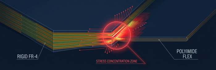
In-plane CTE differs by region. Rigid FR-4 laminate typically runs in a lower, more constrained CTE range in X/Y due to glass-fiber reinforcement, while unreinforced polyimide flex has a comparatively higher and less constrained in-plane CTE. Copper foil and adhesive layers sit in between.
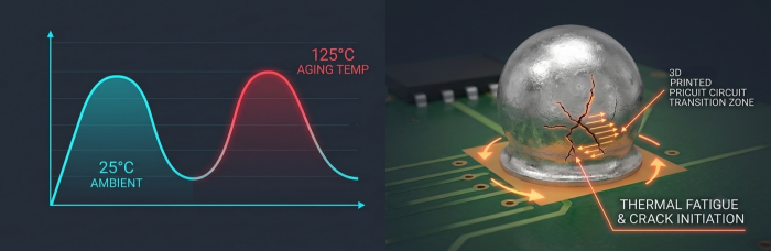
The transition/bend zone is the stress concentrator. During Burn-In or ATE thermal cycling (ambient to elevated setpoints, sometimes with cold-side excursions depending on the test profile), the rigid section and flex section expand and contract at different rates. Because they're mechanically continuous across the transition zone, the differential expansion doesn't average out — it concentrates as shear and peel stress exactly at the rigid-to-flex boundary and at any solder joints or copper features near it.
Cyclic accumulation, not single-event failure. A single thermal excursion rarely fractures a joint. What matters is the number of cycles the assembly sees over its qualification and service life — each cycle adds incremental plastic strain to solder joints and copper traces in the bend region, following classic low-cycle fatigue behavior (Coffin-Manson-type strain accumulation) until a crack initiates and propagates to electrical failure.
Z-axis (through-thickness) CTE compounds the problem in plated through-holes. Where vias or PTHs sit near the rigid-flex transition, Z-axis expansion mismatch between copper barrel and surrounding resin adds a second stress vector on top of the in-plane bend-region stress.
For Burn-In and ATE hardware specifically, this matters more than in a typical rigid-flex application because the board is cycled by design — often for hours per cycle, across many boards, across the operational life of the test cell — rather than exposed to occasional field temperature swings.
Rigid-Flex Assembly Challenges Specific to This Application
Flex-region warpage control
Unsupported flex, especially in thin constructions, is prone to warpage during reflow and during subsequent handling. In our process, warpage-sensitive rigid-flex assemblies are supported through reflow using synthetic stone fixtures, which hold coplanarity of the rigid sections and constrain flex movement without introducing localized thermal mass variation the way metal fixtures can. This is particularly relevant for BGA and fine-pitch components mounted near a rigid-flex boundary, where even modest warpage translates directly into coplanarity-driven solder joint stress at first power-on.
Bend-zone keep-out rules
Solder joints, vias, and copper features should not sit inside the dynamic bend region or its immediate transition zone. As a design-for-manufacturing baseline:
No solder pads, component leads, or SMT footprints within the bend radius plus a transition margin (defined per stack-up and copper weight, not a fixed universal number).
Copper in the flex bend area should use rounded, teardropped, or otherwise stress-relieved trace geometry rather than sharp corners or abrupt width transitions.
Stiffener edges (where used to locally rigidize connector or component zones on the flex) should be chamfered and bonded with adhesive that itself doesn't become a new stress riser at its termination edge.
Copper weight transitions at the rigid-flex boundary should be gradual where the stack-up allows, rather than an abrupt step.
These are standard IPC-2223-aligned rigid-flex design practices, not proprietary rules, but they are the ones most often violated in first-pass ATE/Burn-In board layouts that are adapted from rigid-only designs.
Solder Alloy Selection for Thermal Fatigue Resistance
Alloy choice at BGA and fine-pitch joints in or near the bend-affected zone has a measurable effect on thermal cycling life. Published accelerated thermal cycling studies comparing common Pb-free alloys are a useful reference point (published academic/industry test data, not internal figures):
SAC305 (Sn-3.0Ag-0.5Cu): Comparative ATC studies on BGA joints have found that SAC305 alloy is more likely to withstand thermal cycling loading longer than SAC105, which accumulates creep strain at a faster rate. SAC305 remains a common baseline choice where thermal fatigue resistance is prioritized over cost or rework ease.
SAC105 (Sn-1.0Ag-0.5Cu): The same body of published work shows SAC105 has generally lower accelerated thermal fatigue life than higher-silver alloys under cycling, though it can offer benefits in mechanical shock/drop resistance — a tradeoff that matters more for portable products than for stationary ATE hardware. Researchers examining SAC105 have generally not ruled it out for all applications, noting it may still satisfy field reliability requirements in less thermally aggressive use cases.
SnBi and SAC-SnBi hybrid systems: Published comparative studies on Sn-Bi, hybrid Sn-Bi/SAC, and SAC BGA assemblies have found that homogeneous eutectic SnBi assemblies can exhibit the best thermal cycling reliability among the alloy systems tested, while mixed/hybrid SAC-SnBi joints (SAC balls reflowed with SnBi paste) showed comparatively shorter fatigue life in that same body of work — an important distinction, since "using SnBi" and "using a SAC/SnBi hybrid joint" are not equivalent from a fatigue standpoint.
The practical takeaway for Burn-In/ATE boards: alloy selection at bend-adjacent joints should be matched to the actual thermal profile and cycle count the board will see in service, not selected by default from a general-purpose SMT process recipe.
Closed-Loop Inspection: Handling Rigid-Flex Blind Spots
Rigid-flex geometry creates inspection challenges that a flat rigid board doesn't have — height discontinuities at the rigid-flex step, potential flex-region tilt on the inspection stage, and shadowing at stiffener edges.
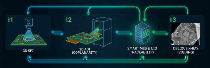
3D SPI is used pre-reflow to verify paste volume and registration at joints near the rigid-flex transition, where paste release can be inconsistent due to local stencil-to-board gap variation at the step-down.
3D AOI, run closed-loop against the SPI data, checks post-placement and post-reflow component position, coplanarity, and solder fillet geometry, with particular attention to components adjacent to the bend zone where warpage-driven defects concentrate.
Off-line X-ray with oblique-angle capability addresses the areas 2D top-down X-ray can't resolve well — BGA and QFN voiding under package bodies located near a rigid-flex step, where the geometry can otherwise obscure void patterns in a straight overhead view.
Smart MES with UID traceability and laser marking ties each board's inspection results, including X-ray voiding records for BGA/QFN packages, back to a unique board identity — relevant for ATE/Burn-In customers who need to correlate a specific board's fabrication and inspection history against field or qualification failures later.
JESD22-A104 and Failure Judgment
JESD22-A104 is the JEDEC standard most commonly referenced for temperature cycling qualification of semiconductor and board-level assemblies, defining cycling profiles (temperature extremes, ramp rate, dwell time) and providing the framework under which cycle-to-failure data is generated and reported. For rigid-flex Burn-In/ATE boards, electrical continuity monitoring during cycling (rather than only end-of-test inspection) is the more sensitive method for catching intermittent opens at bend-region joints before they become hard failures — a resistance-rise threshold, not just a full-open condition, is the more conservative failure criterion, consistent with how much of the published SAC/SnBi comparative data cited above defines "failure" in the first place.
Five DFM Rules for Rigid-Flex ATE/Burn-In Boards
Keep all solder joints, vias, and component footprints outside the bend radius plus transition margin defined for the specific stack-up.
Specify bend-zone copper geometry with stress-relieved (rounded/teardropped) features, avoiding abrupt trace width or copper weight transitions at the rigid-flex boundary.
Match solder alloy selection at bend-adjacent joints to the actual thermal cycling profile and expected cycle count, rather than a default general-purpose alloy.
Support flex regions through reflow with fixturing designed for coplanarity control, and validate post-reflow flatness before proceeding to inspection.
Build inspection coverage — 3D SPI, closed-loop 3D AOI, and oblique-angle X-ray — around the specific geometric blind spots created by the rigid-flex step, not just standard flat-board inspection routines.
If you're bringing up a rigid-flex board for a Burn-In or ATE application and want a second look at bend-zone layout, alloy selection, or inspection coverage before it goes to fabrication, PCBCart's engineering team can review your stack-up and DFM file as part of project quotation.
Ressources utiles
• Streamline Assembly and Improve Reliability with Flexible and Flex-rigid PCBs
• Flexible and Flex-Rigid Printed Circuit Board Applications
• High-Reliability Rigid-Flex PCB for Medical Life Science Instrumentation
• AOI vs. X-Ray Inspection: Which is Right for Your PCB Assembly?


