



Choosing a supplier for a wireless product is not the same as choosing one for a digital board. A line that places 01005 passives and BGAs reliably can still struggle with RF boards, where small process variations show up as performance loss. This RF assembly EMS evaluation checklist is for buyers running wireless PCBA supplier qualification in industrial automation, industrial IoT, life sciences, or semiconductor test equipment. It covers four questions to ask in writing, the warning signs of a supplier without RF experience, and the order profiles where an HMLV partner fits best.
Why Good SMT Does Not Automatically Mean Good RF Assembly
Digital boards forgive small errors. A component slightly off-center rarely matters, because noise margins absorb the variation. RF boards leave much less room:
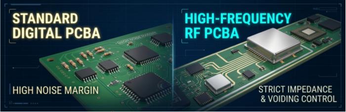
Geometry is part of the circuit. Pad size, trace length, and component position are often tuned to a target impedance or frequency. Placement and solder-volume variation can shift the electrical result.
Solder joints sit in the signal path. Voiding or uneven wetting on RF ground and thermal pads can affect grounding and heat dissipation.
Shielding is a mechanical structure with an electrical job. A skewed or lifted can leaves gaps that undermine its purpose.
Looking perfect is not passing. An RF board can pass visual inspection and still miss its performance target.
So qualifying an RF supplier comes down to one question: how tightly do they control their process, and can they prove it with records?
Four Questions That Reveal Real RF Capability
Ask these in writing. Specific answers are worth more than confident ones.
What is your placement standard for shield cans and frames?
Ask for: a tolerance, where it comes from (component drawing, customer spec, or internal standard), and how it is verified.
A strong answer names a number and a method, explains nozzle and pick-up choices for large or tight-clearance cans, and says how lifted or tilted cans are caught after reflow. IPC-A-610 is the common public reference for acceptability criteria.
A weak answer is “we’re very careful.”
Is your inspection program tuned to RF boards?
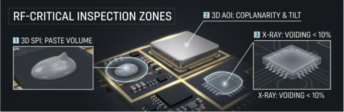
Ask for: how RF-critical features are handled in SPI, AOI, and X-ray.
A strong answer treats matching networks, antenna feed points, and shield frame pads as priority zones. It reviews paste-volume data for those pads and uses X-ray, including oblique-angle views, to check voiding on QFN and BGA RF devices. It also explains how the area under a shield can gets inspected, since optical inspection cannot see it once the can is on.
A weak answer is “we run 3D AOI on everything,” with no mention of RF-specific zones.
Closed-loop 3D SPI and 3D AOI are a solid foundation. The question is whether the program was adapted to your board.
How do you control coplanarity and joints on RF modules?
Ask for: the warpage control approach and the reflow profile record.
Pre-certified wireless modules often use castellated edges, LGA pads, or large ground pads, which are sensitive to warpage in reflow.
A strong answer describes board support (for example, synthetic stone fixtures), a documented thermal profile recorded per job, and a method for verifying joints on hidden pads.
A weak answer is “we handle LGA all the time.”
What is your scope for EMI pre-compliance and RF testing?
Ask for: a written statement of what happens in-house and what goes to a third-party lab.
EMS providers are manufacturers, not accredited RF or EMC labs. A reasonable partner provides unit-level manufacturing records that trace a failing unit back to process data, supports your own test fixtures on the line, and coordinates with the lab you choose.
A weak answer implies certification or calibration-grade measurement without documents to back it up. Verify any such claim on paper.
Five Red Flags
No shield can inspection standard. A vague answer to question 1 usually means no defined process.
One price for every board. RF builds normally need extra setup, inspection, and engineering review. Identical labor hours suggest the work was not scoped.
No engineering questions before the quote. Experienced teams ask about shield drawings, module datasheets, and test requirements.
Generic answers. If a description would fit any SMT board, RF-specific risks have not been considered.
No process records. Without SPI, AOI, reflow, and traceability data linked to each unit, root-cause work after an RF failure is slow.
Which Orders Fit an RF-Capable HMLV Partner
High-mix, low-volume assembly tends to suit:
Prototype to low/mid-volume runs, where process control and engineering review matter more than line speed.
Boards built on pre-certified wireless modules or discrete RF front ends with matching networks.
Designs with shield frames and cans, where placement accuracy and post-reflow inspection are required.
Industrial IoT nodes, power electronics with wireless monitoring, life sciences instruments, and semiconductor test equipment with RF subsystems.
Programs that require unit-level traceability.
Very high-volume, consumer-scale wireless production has different supplier requirements. Fit for any specific order is confirmed in engineering review, not assumed from a profile.
RF Assembly Evaluation Checklist
Copy this into your supplier qualification worksheet:
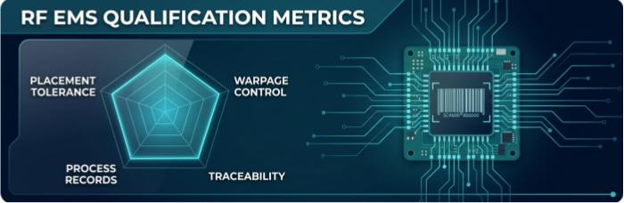
Documented shield can/frame placement tolerance and verification method
Post-reflow inspection for can lift, tilt, and skew
3D SPI and 3D AOI with RF-critical features prioritized
X-ray for BGA/QFN voiding, including oblique views
Warpage control approach for modules and thin boards
Reflow profile recorded per job
UID-based unit traceability linked to process data
Written scope for RF/EMI testing: in-house vs. third-party lab
Quote that separates RF effort from standard effort
Engineering questions raised before quoting
No accreditation claims beyond what is documented
FAQ
What separates SMT capability from RF assembly capability? SMT capability covers placement, soldering, and inspection in general. RF capability adds tighter process control and documented handling of shield cans, modules, and RF-critical joints.
Do EMS providers perform EMC certification testing? Typically not. Accredited EMC and RF testing is done by third-party labs. An EMS partner supports it through process records and fixture coordination.
What should I send for an RF assembly quote? BOM, Gerber and placement files, assembly drawings, shield drawings, module datasheets, and RF test requirements.
Test This Checklist on Your Own Board
The fastest way to evaluate a supplier is with your own design. Send your BOM, Gerber and placement files, shield can/frame drawings, module datasheets, and test requirements. We will review the build against the four questions above and tell you plainly what the process will and will not cover.
[Request an RF Assembly Quote →]
Helpful Resources
• 10 Questions to Ask Any EMS Partner Before Signing: A Technical Due Diligence Framework
• BGA Void Rate Acceptance Reference: IPC-7095D & IPC-A-610 Class Criteria
• MES Traceability Architecture for IEC-Regulated Industrial Electronics
• Setbacks and Solutions in RF PCB Design


